
Page 287 - The Combined Finite-Discrete Element Method
P. 287
270 FLUID COUPLING
Permeable edge
x
d j d
Γ
Bore-hole
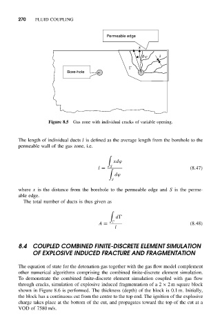
Figure 8.5 Gas zone with individual cracks of variable opening.
The length of individual ducts l is defined as the average length from the borehole to the
permeable wall of the gas zone, i.e.
xdϕ
S
l = (8.47)
dϕ
S
where x is the distance from the borehole to the permeable edge and S is the perme-
able edge.
The total number of ducts is thus given as
d
A = (8.48)
l
8.4 COUPLED COMBINED FINITE-DISCRETE ELEMENT SIMULATION
OF EXPLOSIVE INDUCED FRACTURE AND FRAGMENTATION
The equation of state for the detonation gas together with the gas flow model complement
other numerical algorithms comprising the combined finite-discrete element simulation.
To demonstrate the combined finite-discrete element simulation coupled with gas flow
through cracks, simulation of explosive induced fragmentation of a 2 × 2 m square block
shown in Figure 8.6 is performed. The thickness (depth) of the block is 0.1 m. Initially,
the block has a continuous cut from the centre to the top end. The ignition of the explosive
charge takes place at the bottom of the cut, and propagates toward the top of the cut at a
VOD of 7580 m/s.