
Page 286 - The Combined Finite-Discrete Element Method
P. 286
GAS FLOW THROUGH FRACTURING SOLID 269
For a cross-section at distance l from the entrance to the constant area duct, the corre-
sponding Mach number Ma is calculated using the formula
1
1 1
− (8.42)
2k Ma 2 Ma 2
1
/
2 2 0
k + 1 Ma 2 + (k − 1)Ma 1 fl
+ ln + = 0
4k Ma 1 2 + (k − 1)Ma 2 8A/P
while the pressure is evaluated from the Mach number as follows:
1 2 2 1/2
Ma 1 1 + [(k − 1)/2]Ma
1
p = p 1 2 (8.43)
Ma 1 + [(k − 1)/2]Ma
The above procedure yields both spatial pressure distribution within the gas zone and
the rate of gas loss due to gas flow through the cracks and voids, while all calculations
involve only inexpensive (in terms of CPU time) 1D flow simulation. The density of the
remaining detonation gas decreases due to both gas expansion (i.e. change of the volume
of the gas w = dV/dt,where V is the total volume) and due to the flow of gas, i.e.
m dρ 1 dm m dV
ρ = ; = − (8.44)
V dt V dt V 2 dt
The specific volume is given as v = 1/ρ, thus the change in specific volume is given by
dv 1 dρ V 2
1 dm m dV V dm 1 dV
=− =− − =− + (8.45)
2
2
dt ρ dt m 2 V dt V 2 dt m dt m dt
1 dm 1 dV 1 1
=− v + =− vq + w
m dt m dt m m
where the change of volume of the gas zone w = dV/dt is in actual implementation
calculated from the rate of mechanical work done by the expanding gas. In temporal
discretisation and actual implementation of the algorithm, at every time step, nodal forces
due to the pressure of the detonation gas are calculated together with incremental dis-
placements and nodal velocities. Thus, the work rate is merely calculated as a product of
nodal forces due to gas pressure and nodal velocities.
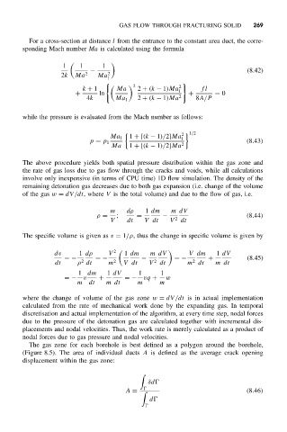
The gas zone for each borehole is best defined as a polygon around the borehole,
(Figure 8.5). The area of individual ducts A is defined as the average crack opening
displacement within the gas zone:
δd
A = (8.46)
d