
Page 283 - The Combined Finite-Discrete Element Method
P. 283
266 FLUID COUPLING
7
6
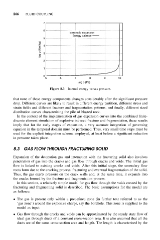
Isentropic expansion
Energy balance
5
log u (Nm/kg) 4 3
2
1
0
5 6 7 8 9 10
log p (Pa)
Figure 8.3 Internal energy versus pressure.
that none of these energy components changes considerably after the significant pressure
drop. Different curves are likely to result in different energy partition, different stress and
strain fields and different fracture and fragmentation patterns, and finally, different sized
distribution curves characterising the pile of blasted rock.
In the context of the implementation of gas expansion curves into the combined finite-
discrete element simulation of explosive induced fracture and fragmentation, these results
imply that for the early stages of expansion, a very accurate integration of governing
equation in the temporal domain must be performed. Thus, very small time steps must be
used for the explicit integration scheme employed, at least before a significant reduction
in pressure takes place.
8.3 GAS FLOW THROUGH FRACTURING SOLID
Expansion of the detonation gas and interaction with the fracturing solid also involves
penetration of gas into the cracks and gas flow through cracks and voids. The initial gas
flow is linked to existing cracks and voids. After this initial stage, the secondary flow
roots form due to the cracking process, fracturing and eventual fragmentation of the solid.
Thus, the gas exerts pressure on the crack walls and, at the same time, it expands into
the cracks formed by the fracture and fragmentation process.
In this section, a relatively simple model for gas flow through the voids created by the
fracturing and fragmenting solid is described. The basic assumptions for the model are
as follows:
• The gas is present only within a predefined zone (in further text referred to as the
‘gas zone’) around the explosive charge, say the borehole. This zone is supplied to the
model as input.
• Gas flow through the cracks and voids can be approximated by the steady state flow of
ideal gas through ducts of a constant cross-section area. It is also assumed that all the
ducts are of the same cross-section area and length. The length is characterised by the