
Page 37 - The Combined Finite-Discrete Element Method
P. 37
20 INTRODUCTION
1
36 different
particle sizes
6 different
0.8
Fraction (weight passing) 0.6 5 different
particle sizes
particle sizes
4 different
particle sizes
0.4
3 different
particle sizes
0.2
2 different
particle sizes
1 particle size
0
0.01 0.1
Normalised particle size
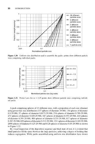
Figure 1.30 Uniform size distribution used to assemble the packs–points show different particle
sizes comprising individual packs.
1 m = 0.5
Fraction (weight passing) 0.6 m = 1.0
0.8
m = 2.25
0.4
0.2
0 m = 3
0.01 0.1 1
Normalised particle size (log scale)
Figure 1.31 Power Law–for m = 2.25 points show different particle sizes comprising individ-
ual packs.
A pack comprising spheres of 13 different sizes, with a proportion of each size obtained
using power law size distribution (137 spheres of diameter 29.988, 136 spheres of diameter
0.9·29.988, 57 spheres of diameter 0.8173·29.988, 274 spheres of diameter 0.789·29.988,
273 spheres of diameter 0.650·29.988, 547 spheres of diameter 0.553·29.988, 410 spheres
of diameter 0.391·29.988, 408 spheres of diameter 0.331·29.988, 817 spheres of diameter
0.287·29.988,829spheresofdiameter0.212·29.988,1211spheresofdiameter0.169·29.988,
2690 spheres of diameter 0.125·29.988 and 6128 spheres of diameter 0.05·29.988) is shown
in Figure 1.32.
By visual inspection of the deposition sequence and final state of rest, it is evident that
small particles fill the space between the large particles, achieving a degree of locking that
reduces segregation. While packs assembled using uniform size distribution have shown