
Page 146 - The Geological Interpretation of Well Logs
P. 146
- THE GEOLOGICAL INTERPRETATION OF WELL LOGS -
have two detectors, a near and far (Figure 10.4). Neutron epithermal neutrons are to be sensed the same detectors
detection is not simple and consists of a two-step process. can be used but covered by a cadmium sheath which
First, the neutrons react with a material to produce effectively absorbs the thermal] neutrons (Table 10.2),
charged, energetic particles; these, in turn, are detected leaving only the epithermal neutrons to pass. The most
through their ionising ability. Thus a detector will consist commonly used tools now use thermal-epithermal neu-
of a target material and a proportional counter. The most tron detection but tools also exist for epithermal detection
common tool detectors are based on the 3He n,p ( i.e. or even gamma rays of capture (Table 10,4).
neutron, proton) reaction in which 3He is used as both a In the tool, both source and detectors are placed on a
target and proportional gas in a counter. skid pressed against the borehole wall (Figure 10.4). The
The efficiency of these counters varies inversely with two detectors are placed along the skid, away from the
the square root of the neutron energy. They therefore source, at a distance calculated from the slowing down
respond primarily to thermal neutrons (lower energy). If length (see Section 10.2) so that they are mainly in the
area of thermal neutron energy in typical formations. The
tool results are given by a ratio of the near detector/far
detector counts, thereby eliminating borehole effects as
much as possible. This is because the far detector read-
(other tool) ings, which contain both hole and formation effects, are
i.e. gamma ray
‘corrected’ by the near detector readings which have
mainly hole effects, leaving only the effects of the forma-
tion. The ratio results are presented on the log as neutron
porosity units after empirical calibration (see Units of
measurement below).
‘AR DETECTOR
Today, the neutron sonde is usually combined in one
tool with the density, gamma ray and caliper as in the
NEAR DETECTOR
f :SOURCE FDC-CNL and LDL-CNL of Schlumberger or the CDL
Y tays ol caplure
‘iphase \hermal neutrons
moderation
eplitharmal neutrons
190-0.025e¥V
fas{ ngulroas
| {other tool) disiance source 4MeV
esp. density
580 om
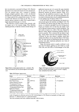
Figure 10.4 A compensated neutron tool — schematic. The Figure 10.5 Spatial distribution of neutrons and disintegration
source and detectors are held pressed against the borehole products around a fast neutron source as used in logging
wall. tools. (Modified from Serra, 1979).
Table 10.4 Neutron logging tools.
*Name Symbol Company Detectors
*Compensated Neutron Log CNL Schlumberger T
Dual Neutron Log DNL (CNT-G) Schlumberger T + E separately
Sidewall Neutron Porosity SNP Schlumberger E
*Compensated Neutron CN Western Atlas T
Sidewall Epitherma] Neutron SWN Western Atlas E
*Compensated Neutron Tool HDSEN Halliburton T
Epithermal Neutron DSEN, SNL Haltiburton E
*Compensated Neutron Sonde CNS BPB T
Epitherma! Neutron Sonde ENS BPB E
{tools with gamma ray detectors such as the GNT (Schlumberger) or NG (Western) are generally no longer used),
Detectors: T = thermal neutron, E = epithermal neutron
*the most commonly used tools, combined especially with the density.
136