
Page 148 - The Jet Engine
P. 148
Controls and instrumentation
fan outlet and turbine exhaust pressures. In some
cases either fan outlet pressure or turbine exhaust
pressure are used alone in place of PINT.
15. The electro-mechanical system indicates a
change in pressure by using transducer capsules
(fig. 12-3) to deflect the centre shaft of the pressure
transducer causing the yoke to pivot about the axis
A.A. This movement is sensed by the linear variable
differential transformer (L.V.D.T.) and converted to an
a.c. electrical signal which is amplified and applied to
the control winding of the servo motor.
16. The servo motor, through the gears, alters the
potentiometer output voltage signal to the E.P.R.
indicator and simultaneously drives the gimbal in the
same direction as the initial yoke movement until the
L.V.D.T. signal to the motor is cancelled and the
system stabilizes at the new setting.
17. The electronic E.P.R. system utilizes two
vibrating cylinder pressure transducers which sense
the engine air pressures and vibrate at frequencies
relative to these pressures. From these vibration
frequencies electrical signals of E.P.R. are computed
and are supplied to the E.P.R. gauge and electronic
engine control system (Part 10).
Engine torque
18. Engine torque is used to indicate the power that
is developed by a turbo-propeller engine, and the
indicator is known as a torquemeter. The engine
torque or turning moment is proportional to the
horse-power and is transmitted through the propeller
reduction gear.
19. A torquemeter system is shown in fig. 12-4. In
this system, the axial thrust produced by the helical
gears is opposed by oil pressure acting on a number
of pistons; the pressure required to resist the axial
thrust is transmitted to the indicator.
20. In addition to providing an indication of engine
power; the torquemeter system may also be used to
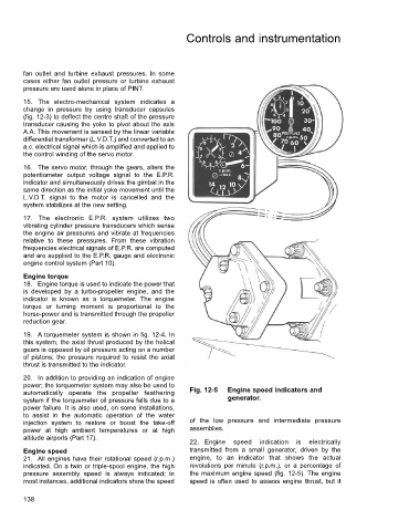
automatically operate the propeller feathering Fig. 12-5 Engine speed indicators and
system if the torquemeter oil pressure falls due to a generator.
power failure. It is also used, on some installations,
to assist in the automatic operation of the water
injection system to restore or boost the take-off of the low pressure and intermediate pressure
power at high ambient temperatures or at high assemblies.
altitude airports (Part 17).
22. Engine speed indication is electrically
Engine speed transmitted from a small generator, driven by the
21. All engines have their rotational speed (r.p.m.) engine, to an indicator that shows the actual
indicated. On a twin or triple-spool engine, the high revolutions per minute (r.p.m.), or a percentage of
pressure assembly speed is always indicated; in the maximum engine speed (fig. 12-5). The engine
most instances, additional indicators show the speed speed is often used to assess engine thrust, but it
138