Page 150 - The Jet Engine
P. 150

Controls and instrumentation


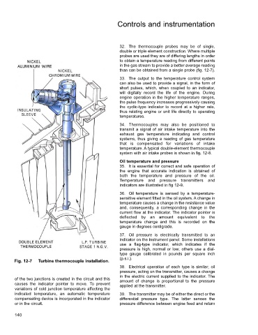
                                                          32. The thermocouple probes may be of single,
                                                          double or triple element construction. Where multiple
                                                          probes are used they are of differing lengths in order
                                                          to obtain a temperature reading from different points
                                                          in the gas stream to provide a better average reading
                                                          than can be obtained from a single probe (fig. 12-7).
                                                          33. The output to the temperature control system
                                                          can also be used to provide a signal, in the form of
                                                          short pulses, which, when coupled to an indicator,
                                                          will digitally record the life of the engine. During
                                                          engine operation in the higher temperature ranges,
                                                          the pulse frequency increases progressively causing
                                                          the cyclic-type indicator to record at a higher rate,
                                                          thus relating engine or unit life directly to operating
                                                          temperatures.
                                                          34. Thermocouples may also be positioned to
                                                          transmit a signal of air intake temperature into the
                                                          exhaust gas temperature indicating and control
                                                          systems, thus giving a reading of gas temperature
                                                          that is compensated for variations of intake
                                                          temperature. A typical double-element thermocouple
                                                          system with air intake probes is shown in fig. 12-8.

                                                          Oil temperature and pressure
                                                          35. It is essential for correct and safe operation of
                                                          the engine that accurate indication is obtained of
                                                          both the temperature and pressure of the oil.
                                                          Temperature and pressure transmitters and
                                                          indicators are illustrated in fig 12-9.
                                                          36. Oil temperature is sensed by a temperature-
                                                          sensitive element fitted in the oil system. A change in
                                                          temperature causes a change in the resistance value
                                                          and, consequently, a corresponding change in the
                                                          current flow at the indicator. The indicator pointer is
                                                          deflected by an amount equivalent to the
                                                          temperature change and this is recorded on the
                                                          gauge in degrees centigrade.

                                                          37. Oil pressure is electrically transmitted to an
                                                          indicator on the instrument panel. Some installations
                                                          use a flag-type indicator, which indicates if the
                                                          pressure is high, normal or low; others use a dial-
                                                          type gauge calibrated in pounds per square inch
                                                          (p.s.i.).
        Fig. 12-7  Turbine thermocouple installation.
                                                          38. Electrical operation of each type is similar; oil
                                                          pressure, acting on the transmitter, causes a change
                                                          in the electric current supplied to the indicator. The
        of the two junctions is created in the circuit and this  amount of change is proportional to the pressure
        causes the indicator pointer to move.  To prevent  applied at the transmitter.
        variations of cold junction temperature affecting the
        indicated temperature, an automatic temperature   39. The transmitter may be of either the direct or the
        compensating device is incorporated in the indicator  differential pressure type.  The latter senses the
        or in the circuit.                                pressure difference between engine feed and return

        140
   145   146   147   148   149   150   151   152   153   154   155