
Page 153 - The Jet Engine
P. 153
Controls and instrumentation
shaft failure occur, are but two examples. On some
engine types, the fuel system is fitted with a control
to enable the engine to be operated by manual
throttling should a main fuel system failure occur.
49. In addition to a fire warning system (Part 14), a
number of other audible or visual warning systems
can be fitted to a gas turbine engine. These may be
for low oil or fuel pressure, excessive vibration or
overheating. Indication of these may be by warning
light, bell or horn. A flashing light is used to attract the
pilot's attention to a central warning panel (C.W.P.)
where the actual fault is indicated.
50. Other instruments and lights warn the pilot of
the selected position of the thrust reverser, the fan
reverser or the afterburner variable nozzle, when
applicable. Gauges also inform the pilot of such
things as hydraulic pressure and flow and generator
output, which are vital to the correct operation of the
aircraft systems.
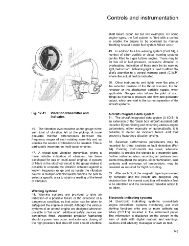
Fig. 12-11 Vibration transmitter and Aircraft integrated data system
indicator. 51. The aircraft integrated data system (A.I.D.S.) is
an extension of the 'black box' aircraft accident data
recorder. By monitoring and recording various engine
46. The vibration level recorded on the gauge is the parameters, either manually or automatically, it is
sum total of vibration felt at the pick-up. A more possible to detect an incipient failure and thus
accurate method differentiates between the prevent a hazardous situation arising.
frequency ranges of each rotating assembly and so
enables the source of vibration to be isolated. This is 52. Selected performance parameters may be
particularly important on multi-spool engines. recorded for trend analysis or fault detection (Part
24). Existing instruments are used, wherever
47. A crystal-type vibration transmitter, giving a possible, to provide the signals to a magnetic tape.
more reliable indication of vibration, has been Further instrumentation, recording air pressure from
developed for use on multi-spool engines. A system points throughout the engine, oil contamination, tank
of filters in the electrical circuit to the gauge makes it contents and scavenge oil temperature, may be
possible to compare the vibration obtained against a provided as required for flight recording,
known frequency range and so locate the vibration
source. A multiple-selector switch enables the pilot to 53. After each flight the magnetic tape is processed
select a specific area to obtain a reading of the level by computer and the results are analyzed. Any
of vibration. deviation from the normal condition will enable a fault
to be identified and the necessary remedial action to
be taken.
Warning systems
48. Warning systems are provided to give an
indication of a possible failure or the existence of a Electronic indicating systems
dangerous condition, so that action can be taken to 54. Electronic indicating systems consolidate
safeguard the engine or aircraft. Although the various engine indications, systems monitoring, and crew
systems of an aircraft engine are designed wherever alerting functions onto one or more cathode ray
possible to 'fail safe1, additional safety devices are tubes (C.R.T.'s) mounted in the instrument panel.
sometimes fitted. Automatic propeller feathering The information is displayed on the screen in the
should a power loss occur, and automatic closing of form of dials with digital readout and warnings,
the high pressure fuel shut-off cock should a turbine cautions and advisory messages shown as text.
143