
Page 149 - The Jet Engine
P. 149
Controls and instrumentation
26. In addition to providing an indication of rotor
speed, the current induced at the speed probe can
be used to illuminate a warning lamp on the
instrument panel to indicate to the pilot that a rotor
assembly is turning. This is particularly important at
engine start, because it informs the pilot when to
open the fuel cock to allow fuel to the engine. The
lamp is connected into the slatting circuit and is
illuminated during the starting cycle.
Turbine gas temperature
27. The temperature of the exhaust gases is always
indicated to ensure that the temperature of the
turbine assembly can be checked at any specific
operating condition. In addition, an automatic gas
temperature control system is usually provided, to
ensure that the maximum gas temperature is not
exceeded (Part 10).
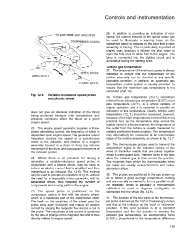
Fig. 12-6 Variable-reluctance speed probe
and phonic wheel. 28. Turbine gas temperature (T.G.T.) sometimes
referred to as exhaust gas temperature (E.G.T.) or jet
pipe temperature (J.P.T.), is a critical variable of
engine operation and it is essential to provide an
does not give an absolute indication of the thrust indication of this temperature. Ideally, turbine entry
being produced because inlet temperature and temperature (T.E.T.) should be measured; however,
pressure conditions affect the thrust at a given because of the high temperatures involved this is not
engine speed. practical, but, as the temperature drop across the
turbine varies in a known manner, the temperature at
23. The engine speed generator supplies a three- the outlet from the turbine is usually measured by
phase alternating current, the frequency of which is suitably positioned thermocouples. The temperature
dependent upon engine speed. The generator output may alternatively be measured at an intermediate
frequency controls the speed of a synchronous stage of the turbine assembly, as shown in fig. 12-7.
motor in the indicator, and rotation of a magnet
assembly housed in a drum or drag cup induces 29. The thermocouple probes used to transmit the
movement of the drum and consequent movement of temperature signal to the indicator consist of two
the indicator pointer, wires of dissimilar metals that are joined together
inside a metal guard tube. Transfer holes in the tube
24. Where there is no provision for driving a allow the exhaust gas to flow across the junction.
generator, a variable-reluctance speed probe, in The materials from which the thermocouples wires
conjunction with a phonic wheel, may be used to are made are usually nickel-chromium and nickel-
induce an electric current that is amplified and then aluminium alloys.
transmitted to an indicator (fig. 12-6). This method
can be used to provide an indication of r.p.m. without 30. The probes are positioned in the gas stream so
the need for a separately driven generator, with its as to obtain a good average temperature reading
associated drives, thus reducing the number of and are normally connected to form a parallel circuit.
components and moving parts in the engine. An indicator, which is basically a millivoltmeter
calibrated to read in degrees centigrade, is
25. The speed probe is positioned on the connected into the circuit (fig. 12-8).
compressor casing in line with the phonic wheel,
which is a machined part of the compressor shaft. 31. The junction of the two wires at the thermocou-
The teeth on the periphery of the wheel pass the ple probe is known as the 'hot' or 'measuring' junction
probe once each revolution and induce an electric and that at the indicator as the 'cold' or 'reference'
current by varying the magnetic flux across a coil in junction. If the cold junction is at a constant
the probe. The magnitude of the current is governed temperature and the hot junction is sensing the
by the rate of change of the magnetic flux and is thus exhaust gas temperature, an electromotive force
directly related to engine speed. (E.M.F.), proportional to the temperature difference
139