
Page 154 - The Jet Engine
P. 154
Controls and instrumentation
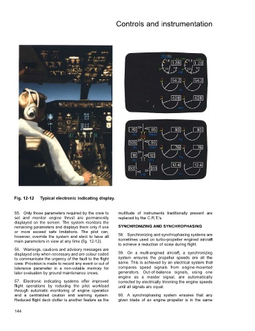
Fig. 12-12 Typical electronic indicating display.
55. Only those parameters required by the crew to multitude of instruments traditionally present are
set and monitor engine thrust are permanently replaced by the C.R.T.'s.
displayed on the screen. The system monitors the
remaining parameters and displays them only if one SYNCHRONIZING AND SYNCHROPHASING
or more exceed safe limitations. The pilot can,
however, override the system and elect to have all 58. Synchronizing and synchrophasing systems are
main parameters in view at any time (fig. 12-12). sometimes used on turbo-propeller engined aircraft
to achieve a reduction of noise during flight.
56. Warnings, cautions and advisory messages are
displayed only when necessary and are colour coded 59. On a multi-engined aircraft, a synchronizing
to communicate the urgency of the fault to the flight system ensures the propeller speeds are all the
crew. Provision is made to record any event or out of same. This is achieved by an electrical system that
tolerance parameter in a non-volatile memory for compares speed signals from engine-mounted
later evaluation by ground maintenance crews. generators. Out-of-balance signals, using one
engine as a master signal, are automatically
57. Electronic indicating systems offer improved corrected by electrically trimming the engine speeds
flight operations by reducing the pilot workload until all signals are equal.
through automatic monitoring of engine operation
and a centralized caution and warning system. 60. A synchrophasing system ensures that any
Reduced flight deck clutter is another feature as the given blade of an engine propeller is in the same
144