
Page 123 -
P. 123
The Practical Pumping Handbook ............... ,r .... : ..................
I I I I ,1>
1
TO SEAL
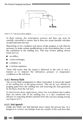
Figure 6.16: Seal recirculation diagram
In these systems, the recirculation pressure and flow rate must be
carefully controlled to ensure that it does not create harmful velocities
around and onto the seal.
Depending on the condition and nature of the product, it will often be
necessary to make certain modifications to the recirculation line, to suit
the conditions in the stuffing box. This may involve adding various
items such as;
9 an orifice,
9 a heat exchanger,
9 a strainer, or
9 a cyclone separator.
These will ensure that the liquid is delivered to the seal, in such a
manner as to improve the lubrication, pressure or temperature
conditions at the seal faces.
6.4.2 Reverse flush
The reverse flush arrangcmcnt is often overlooked. It moves the liquid
in the stuffing box to thc pump suction. This can bc very effective in
purging gases from the stuffing box and removing the heat generated
by the faces, from the seal area.
In intermittent slurry applications, where the recirculation line is taken
from the lowest side of the stuffing box, it is also considered very
effective in removing abrasive particles from the seal area during startup
(see Figure 6.17).
6.4.3 Seal quench
Unlike the Flush, the Seal Quench never enters the process line. It is
designed to remove any leakage from the outside of the seal faces that
m 102