
Page 190 -
P. 190
Pump Installation 8 Piping
. . . . . . . . . . . . . . . . . . . . . . . . . . . . . . . . . . . . . . . . . . . . . . . . .
It has been argued that piping procedures are not important because
many pumps are piped incorrectly, but are operating quite satisfactorily.
That doesn't make a questionable piping practice correct, it merely
makes it lucky.
Some installations appear as if the pumps have been squeezed into a
corner out of the way, and the pipes threaded in and out, without any
consideration for fluid flow patterns. This should be strenuously
avoided.
When a pump is running, the liquid must arrive at the impeller eye with
the right pressure and the smooth uniform flow that is necessary for
reliable operation. This depends a great deal on the suction piping
design.
0.2.1 Location
The location of the pump relative to its suction source is critical to its
ultimate reliability. Every pump should be located as close to its suction
source as possible in order to reduce the effect of friction losses on the
NPSH available. However it must also be far enough away from the
suction source to ensure that correct piping practices can be followed.
These piping practices involve a number of simple rules which, if
followed, will eliminate a significant percentage of all potential pump
problems.
10.2.1.1 Pipe size
The pipe diameter on both the inlet and the outlet sides of the pump
should be at least one size larger than the nozzle itself.
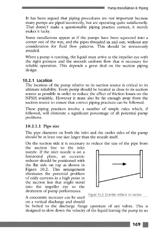
On the suction side it is necessary to reduce the size of the pipe from
the suction line to the inlet
nozzle. If the inlet nozzle is on a
horizontal plane, an eccentric
reducer should be positioned with
the flat side on top as shown in W
Figure 10.2. This arrangement
eliminates the potential problem
of eddy currents in a high point in
the suction line that might travel
into the impeller eye to the
detriment of pump performance.
Figure 10.2: Eccentric reducer on suction
A concentric increaser can be used
on a vertical discharge and should
be bolted to the discharge flange upstream of any valves. This is
designed to slow down the velocity of the liquid leaving the pump to an
....... 169