
Page 191 -
P. 191
The Practical Pumping Handbook
acceptable rate within the system itself and, in particular, through the
check valve and isolating valve. The slower velocity (usually lower than
10 ft./see.) reduces friction losses in the line and minimizes power
draw at the pump.
10.2.1.2 Suction elbows
Eliminate elbows mounted on the inlet nozzle of the pump.
Much discussion has taken place over the acceptable configuration of an
elbow on the suction flange of a pump. Let's simplify it. There isn't
one!
There is always an uneven flow in an elbow, and when one is installed
on the suction of any pump, it introduces that uneven flow into the eye
of the impeller. This can create turbulence and air entrainment, which
can result in impeller damage and vibration.
The only thing worse than one
elbow on the suction of a pump
is two elbows on the suction of a
pump, particularly if they are
positioned close together, in
planes at right angles to each
other. This creates a spinning
effect in the liquid that is carried
into the impeller and causes
turbulence, inefficiency and
vibration. Figure 10.3: Two elbows on pump suction
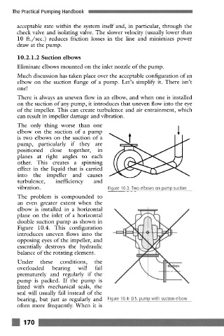
The problem is compounded to
an even greater extent when the
elbow is installed in a horizontal
plane on the inlet of a horizontal
double suction pump as shown in
Figure 10.4. This configuration
introduces uneven flows into the
opposing eyes of the impeller, and
essentially destroys the hydraulic
balance of the rotating element.
Under these conditions, the
overloaded bearing will fail
prematurely and regularly if the
pump is packed. If the pump is
fitted with mechanical seals, the
seal will usually fail instead of the
bearing, but just as regularly and Figure 10.4: D.S. pump with suction elbow
often more frequently. When it is
170