
Page 199 -
P. 199
The Practical Pumping Handbook . . . . . . . . . . . . . . . . . .
For both of these methods, a flexible coupling will be required that will
be able to accommodate the total amount of misalignment anticipated.
10.3.4 Typical acceptance values
Bringing the motor shaft into alignment with the pump shaft usually
involves moving the front and rear feet of the motor, vertically and
horizontally, until the shafts arc aligned within acceptable tolerances.
In addition to such data as the speed of rotation, horsepower, spacer
length, shaft size, etc., acceptable alignment tolerances depend to a
large extent on the level of pump reliability that is expected by the
pump user. Consequently, every end user should develop their own
acceptance levels that provide their desired outcomes.
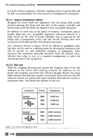
The tolerances shown in Figure 10.13 are offered as guidelines only,
but they can be used as a starting point for developing tolerances that
will be specific to each individual company or equipment. They
represent the maximum allowable deviation from the desired value,
whether that value is zero or a targeted misalignment to allow for
thermal growth of the equipment.
10.3.5 Run out
With the coupling disconnected, mount the magnetic base of the dial
indicator to the motor half coupling, position the indicator on the
pump half coupling, and center the indicator plunger. Rotate the pump
shaft until the dial indicator reaches a maximum travel and zero the dial
indicator. Rotate the pump shaft again until the dial indicator reaches a
maximum value. This shows the amount of run out.
Condition R.P.M. Tolerances
Parallel 3600 0.002 ins
Misalignment
1800 0.004 ins
1200 0.005 ins
Angular 3600 0.004 ins/inch
Misalignment
1800 0.006 ins/inch
1200 0.008 ins/inch
Figure 10.13. Alignment tolerances table
! 178