
Page 197 -
P. 197
The Practical Pumping Handbook
involved in this resistance can damage beatings, seals and even the shaft
itself. It should also be noted that the restoring forces are proportional
to misalignment. In other words the larger the misalignment of the
shafts the greater the forces on the bearings, etc. Consequently, the
shafts of the pump and driver should be aligned as closely as possible to
provide optimum reliability of the pump.
In most pump installations, it is accepted that perfect shaft alignment is
unlikely throughout the operating cycle. In such conditions, the
coupling selection should be able to accommodate the maximum
amount of the misalignment anticipated. This should be confirmed
with the supplier as even flexible couplings have limitations which are
often ignored and result in premature bearing failure and unreliable
operation.
10.3.2 Shaft offset and angularity
Alignment occurs when two lines that are superimposed on each other,
form a single line. Misalignment is a measure of how far apart the two
lines arc from forming that single line. The two lines we are concerned
with here are the centerlines of the pump shaft and the driver shaft. In
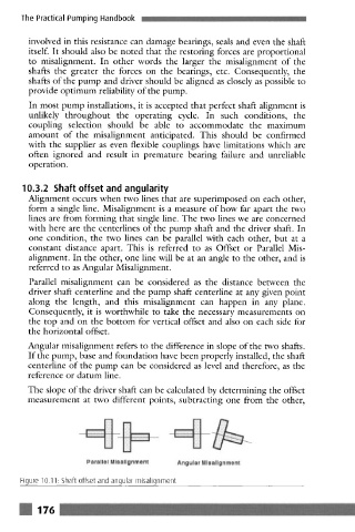
one condition, the two lines can be parallel with each othcr, but at a
constant distance apart. This is referred to as Offset or Parallel Mis-
alignment. In the other, one line will be at an angle to the other, and is
referred to as Angular Misalignment.
Parallel misalignmcnt can be considered as the distance between the
driver shaft centerline and the pump shaft centerline at any given point
along the length, and this misalignment can happen in any plane.
Consequently, it is worthwhile to take the ncccssary mcasurcmcnts on
the top and on the bottom for vertical offset and also on each side for
the horizontal offset.
Angular misalignment refers to the difference in slope of the two shafts.
If the pump, base and foundation havc been properly installed, the shaft
ccnterlinc of the pump can be considered as level and therefore, as the
reference or datum line.
The slope of the driver shaft can be calculated by determining the offset
measurement at two different points, subtracting one from the other,
. ................... ................... .
!:.:.:.:.:.:.:.:.:.:! U
.................... "d B" ....................
Parallel Mlsallgnment Angular Mlsallgnment
Figure 10.11: Shaft offset and angular misalignment
! 176