Page 116 - The Tribology Handbook
P. 116

Selection of rolling bearings                                    A20


                 Speed limits for radial bearings                      1
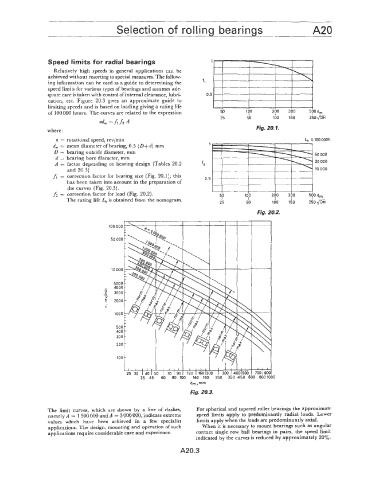
                   Relatively  high speeds in  general  applications  can  be
                 achieved without resorting to special measures. The follow-
                 ing information can be used  as a guide to determining the   f,
                 speed limits for various types of bearings and assumes ade-
                 quate care is taken with control ofinternal clearance, lubri-   0.5
                 cation,  etc.  Figure  20.3 gives  an  approximate  guide  to
                 limiting speeds and is based on loading giving a rating life
                 of 100 000 hours. The curves are related  to the expression


                 where :                                                              Fig. 20.7.
                    n = rotational speed, revlrnin                                                    L.  L 100 OOOh
                   d,  = mean diameter of bearing, 0.5 (D+d) mm        1
                   D = bearing outside diameter, mm
                    d = bearing bore diameter, mm                                                         50 000
                   A  = factor depending on  bearing design  (Tables 20.2   t                             20 000
                       and 20.3)                                                                          10 000

                                                         '
                                          1
                   fl  = correction factor for bearing size (Fig. 20.1); this   0.5 1
                       has belen  taken into account in the preparation  of                       I
                       the cui-ves (Fig. 20.3).                            I       I  I     I            1
                                                                                                  I
                                                                                   I
                                                                           t
                                                                                            I
                   f2 = correction factor for load  (Fig. 20.2).        I  SO     100      200   300    5bOd,
                                                                                                  I
                                                                                            I
                                                                           I
                                                                                   I
                       The rating life Lh is obtained from the nomogram.
                                                                          25       50      100   150    240m
                                                                                      Rg. 20.2.


                                                                Rg. 20.3.


                 The  limit  CUI  ves,  which are  shown  by  a  line of  dashes,   For spherical and tapered roller bearings the approximate
                 namely A = 1 500 000 and A  = 3 000 000, indicate extreme   speed  limits apply to predominantly  radial loads.  Lower
                 values  which  have  been  achieved  in  a  few  specialist   limits apply when the loads are predominantly  axial.
                 applications. The design, mounting and operation of such   When it is necessary to mount bearings such as angular
                 applications require considerable care and experience.   contact single row  ball  bearings in  pairs,  the speed limit
                                                                  indicated  by  the curves is reduced by approximately 20%.
                                                            A20.3
   111   112   113   114   115   116   117   118   119   120   121