
Page 112 - The Tribology Handbook
P. 112
Gas bearings AI9
0. E
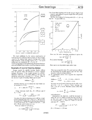
Use of two short bearings side by side can give higher load
capacity and stiffness for given length but with greatly
increased air flow.
0.7 Air flow rate is given for bearing with 6/49 = 1, lib =
and Ct = 25 pm (0.001 in).
0.6 0.5
0.5 0.4
”3 0.4
0.3
.-
E
mL
0.3 4-
L
x-
5 0.2
0.2
0.1
0.1
I
_1 I 0 1 2 3 4 5 6 7 8 b a r
05 1.0 1.5 2.0 2.5 3.0 SUPPLY PRESSURE, pf
OVERALL. LENGTH TO DIAMETER RATIO, byD
Flow rate for other operating conditions is given by
._
The load coefficient CL for various combinations of Q=Q*.(P> 30
C
half and quarter stations is used to assess the best arrange- C$ b
ment for the highest load capacity bearing with a fixed For 4 station bearings
shaft diameter. Load carrying capacity at E = 0.5 and 8
orifices per row (pocketed) W = C,. Pf . D2.
For low pumping power use halfstations. Forgreaterload cap-
acity and stiffness from smallest area bD use quarter stations. Flow rate is not dependent upon orifice type.
Example olf journal bearing design
Design wanted for spindle bearing. Radial stiffness This is an acceptable value. We could increase stiffness
must be greater than 200 kN/mm to achieve required by increasing the number above 8 per row but may
resonant frequency; 5 bar supply pressure is available. introduce manufacturing problems.
Minimum shaft dia. set by shaft stiffness is 100 mm and (ii) If unpocketed orifices were required for improved
minimum practicable clearance C, = 30 pm. What is stability, then :
the shortest length of bearing which can be used? 2W
W Stiffness = -__ .’. W = 3.1500 = 2250 N
(4 Stiffness = -, and CL = f 0.3 = 0.45.
cd/4
therefore bearing can be defined by load which can We must use two 4 station bearings side by side; over-
be carried at E = 0.5. all b‘/D = 1.2, b‘ = 120 mm. Each bearing has
(30. b/D = 0.6. d* = 0.145. Therefore actual orifice dia.
i.e. W= (200.106) -- = 1500 N. required
4
30 1
Using minimum shaft dia., D = 100 mm and if d = 0.145 - - = 0.29 mm
Pf = 5 ba.r 25 0.6
at 8 orifices/row.
Alternatively the shaft dia. could be increased to
allow the use of a single 4 station bearing, saving on
Therefore the shortest bearing system will be, a single air flow rate; since a short bearing is required take
a station bearing with b/D := 0.8, i.e. b = 80 mm from C, = 0.32 at b/D = 1. Then W = 0.32 x 5 x lo5 D2
the graph of 6,. Orifice size for this bearing is obtained and since W = 2250 N,
via the graph of d *, d * = 0.085 mm for b/D = 1 and
C) = 25 pm and 8 orifices per row. 2250
D2 = = 1.41 IO-’ mZ7
With ou!r values for b/D and Cd; 0.32 x 5 x io5
t ‘1 f D = 119mm, b = 119mm.
d = 0.085 (g) (,G)= 0.125 rnm.
A19.5