
Page 111 - The Tribology Handbook
P. 111
AI9 Gas bearinas
I
External y pressurised -gas
journal bearings
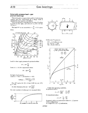
This section gives an approximate guide to load carrying
capacity and flow requirements for a design which is
optimised for load capacity and stiffness.
Values are given for a bearing with two rows of 8 orifices
P;
as shown on the right, and with 116 = i, = 6.9 bar
(100 p.s.i.).
2e
The load W* at an eccentricity E = - = 0.5 is given
cd
below.
Q* FLOW cfm 1.0 0.8 0.6 0.4 b
600 * Orifice size d * is given for:
500 3 b/D = 1,8 orifices per row
400 air, 15"C,p0 = 1 bar
300 2 Cj = 25 pm (0.001 in)
200
ORIFICE SIZE VALID FOR
8- V, AND V, STATION BEARINGS
7-
20 40 60 80 100 li0 140
LENGTH, b. mm 6-
Load for other supply pressures for pocketed orifices
P
w= w*I
Pf
Load at E = 0.5 for unpocketed orifices
for higher load capacity :
(load at E = 0.9) = 1.28 (load at E = 0.5).
(load at E = 0.5)
Stiffness = P ,bar
cd/4 2 , f? 6 8
I I I 1 I
Flow Q* is given for Ct; = 25 pm (0.001 in), air, 15"C, 0 20 40 60 80 100 120
Po = 1 bar. Pf. p.s.i.
(2);
At other clearances, flow Q = Q* - Under other operating conditions,
for pocketed orifices :
For other numbers of orifices per row use graph below.
for unpocketed orifices
' I In general, orifices are positioned at either l/b = 4 (quarter
0.6 I I I
4 0 12 14 station configuration).
N, NUMBER OF ORIFICES PER ROW or a single row at l/b = (half station)
A19.4