
Page 106 - The Tribology Handbook
P. 106
Hydrostatic bearings A18
10
7
5
-
-
A B3
2
I
0.7
I 1.5 2 3 5 10 Q)
B/L B/L
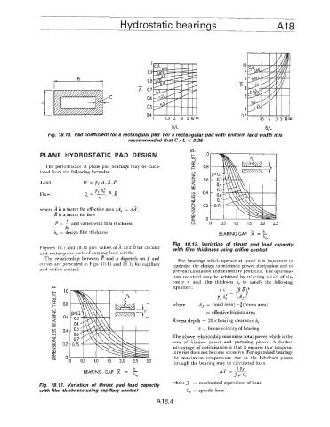
Fig. I$. 10. Pad coefficient for a rectangular pad. For a rectangular pad with uniform land width it is
recommended that C / 6 < 0.25
In
PLANE HYDROSTATIC PAD DESIGN t;;
2
The performance of plane pad bearings may be calcu- F
lated from the following formulae: c3
z
Load : W = A.A.P 2
3 #
Flow: Q= Pdh,p.g In
m
rl LLI
-J
Z
Q
where 2 is a factor for effective area (A, = AI) v)
B is a factor for flow zi
E
- P - "
63 = - and varies with film thickness n 0 0.5 1-0 1.5 2.0 2.5
Pf
h, = design film thickness BEARINGGAP x = !l-
h0
Fig. 18.12. Variation of thrust pad load capacity
Figures 18.7 and 18.10 give values of 3 and sfor circular with film thickness using orifice controi
and rectangular pads of varying land widths.
The relationship between P :and h depends on /I and For bearings which operate at speed it is important to
curves are presented in Figs. 18.1 1 and 18.12 for capillary optimise the design to minimise power dissipation and to
and orifice control. prevent cavitation and instability problems. The optimisa-
tion required may be achieved by selecting values of vis-
cosity 9 and film thickness h, to satisfy the following
la I .o equation: /3B +
$ %= LiJ
2
I 0.8 where A~ = (total area) -3 (recess area)
k-
c3
z = effective friction area
lY 0h
4 Recess depth = 20 x bearing clearance h,
Lu
rn u = linear velocity of bearing
3 0.4
Lu
1 The above relationship minimises total power which is the
2 0.2 sum of friction power and pumping power. A further
advantage of optimisation is that it ensures that tempera-
5 ture rise does not become excessive. For optimised bearings
E n the maximum temperature rise as the lubricant passes
" 0 0.5 1.0 1.5 2.0 2.5 3.0 through the bearing may be calculated from
h
BEARING GAP = -
hcJ
where 3 = mechanical equivalent of heat
Fig. 18.11. Variation of thrust pad load capacity
with film thickness using capillary control C, = specific heat
A18.4