
Page 105 - The Tribology Handbook
P. 105
A18 Hydrostatic bearings
Calculation of bearing stiffness I
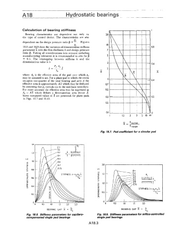
Bearing characteristics are dependent not only on
the type of control device. The characteristics are also
PO
dependent on the design pressure ratio p = - . Figures
Pf
18.8 and 1&9 show the variation of dimensionless stiffness 0.8
parameter A with the film thickness h and design pressure
ratio $. Taking all considerations into account including
manufacturing tolerances it is recommended to aim for p
= 0.5. The relation_ship between stiffness X and the
dimensionless value h is
0.6
Pf Ae
L=- .I -
ho B x
where A, is the effective area of the pad over which pf
may be assumed to act. For a plane pad in which the recess
occupies one-quarter of the total bearing pad area A the 0.4
effective area is approximately A/2 which may be deduced
by assuming thatpf extends out to the mid-land boundary.
For more accuracy the effective area may be expressed as
A, = AA which defines a dimensionless area factor 6.
Some computed values of A are presented for plane pads 0.2
in Figs. 18.7 and 18.10.
0
I 1.5 2 3 5 IO
-
R - ROUTER
INNER
Fig. 18.7. Pad coefficient for a circular pad
1.4
1.2
I4
Ln 1.0
W 2D
v)
t I
0.8 I4
v) 1.5
w
v)
v) z
!A
v)
1 0.6 Y
P c
v)
v)
2 2 1.0
0.4 W
0 I
8 05
0.2 s
0
0 I .o
0 0.5 1.0 1.5 2.0 2.5 0 0.5 1.5 20
h
BEARING GAP 2 = iio BEARING GAP =
ho
Fig. 18.8. Stiffness parameters for capillary- Fig. 18.9. Stiffness parameters for orifice-controlled
compensated single pad bearings single pad bearings
AI 8.3