
Page 101 - The Tribology Handbook
P. 101
A17 Tilting pad thrust bearings
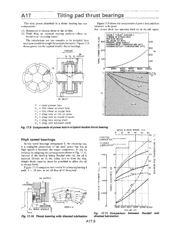
The total power absorbed in a thrust bearing has two Figure 17.9 shows the components ofpower loss and their
components : variation with speed.
Note: always check that operating loads are in the safe region.
(1) Resistance to viscous shear in the oil film.
(2) Fluid drag on exposed moving surfaces-often re-
DOUELE THRUS? ASSEMBLY
ferred to as 'churning losses'. I
2 RINGS OF 8 PADS EACH
PAD SIZE 60mm
The calculations are too complex to be included here x- 300 OIL 25CSt AT 60'C
and data should be sought from manufacturers. Figure 17.8 SPECIFIC LOAD 3MN/m2 400
HOUSING INLET TEMPERATURE 5OoC
shows power loss for typical double thrust bearings. HOUSING OUTLET TEMPERATURE 67OC
300
THRUST
OIL
yi H3 yz OUTLET
OIL INLET
H = total power loss
H = film shear at main face
H, = film shear at surge face
H, = drag loss at rim of collar
H, = drag loss at inside of pads
H, = drag loss along shaft
H, = drag loss between pads
Fig. 17.9 Components of power loss in a typical double thrust bearing
MEAN SLIDING SPEED, m/S
10 20 30 40 50 60
130 ou
FLOODED - - - - - -
High speed bearings LUBRICATION 120 t-
In low speed bearings component 2, the churning loss, LT
3
is a negligible proportion of the total power loss but at LUBRICATION 110 $
high speeds it becomes the major component. It can be LL
w
reduced by adopting the arrangement shown in Fig. 17.10. a
Instead of the bearing being flooded with oil, the oil is 100 +
injected directly on to the collar face to form the film. 0
Ample drain capacity must be provided to allow the oil 90 2
to escape freely. 5
Figure 17.1 1 compares test results for a bearing having 8 80 $
pads, b = 28 mrn, at an oil flow of 45 litreslrnin. X
U
70
OIL SUPPLY
2000 4000 6000 8000 10,000 12,000
revs per rnin
Fig. 17.11. Comparison between flooded and
Fig. 17. IO. Thrust bearing with directed lubrication directed lubrication
A17.5