
Page 98 - The Tribology Handbook
P. 98
Tilting pad thrust bearings A17
SELECTION OF THRUST BEARING SIZE
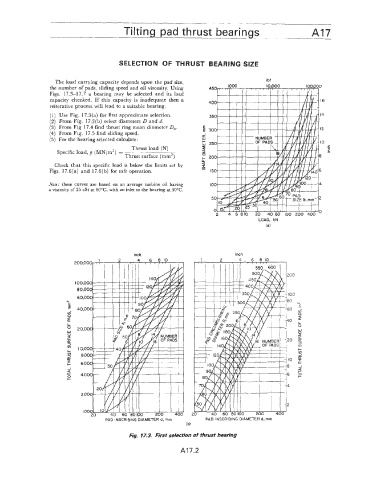
The load ca.rrying capacity depends upon the pad size, ibf
the number of‘ pads, sliding speed and oil viscosity. Using 450 1000 10,000 l00.000
Figs. 17.3-17.7 a bearing may be selected and its load
capacity checlked. If this capacity is inadequate then a 400 16
reiterative process will lead to a suitable bearing.
(1) Use Fig. 17.3(a) for first approximate selection. 350 14
(2) From Fig. 17.3(b) select diameters D and d.
(3) From Fig 17.4 find thrust ring mean diameter D,. 12
(4) From Fig. 17.5 find sliding speed. s 300
(5) For the bearing selected calculate: 250 10
Thrust load (N) 5 r
-
C
Specific load, p (MN/m2) =
Thrust surface (mm’) E 8
+ 200
Check that this specific load is below the limits set by 2
I
Figs. 17.6(a) and 17.6(b) for safe operation. * 150 6
Note: these curves are based on an average turbine oil having IO0 4
a viscosity of 25 cSt at 60°C, with an inlet to the bearing at 50°C.
50 2
0 0
2 4 6 810 20 40 60 100 200 400
LOAD, kN
(a)
inch
--
PAD INSCRIBING DIAMETER d, mm PAD INSCRIBING DIAMETER d, mm
(b)
Fig. 17.3. First selection of thrust bearing
A’l7.2