
Page 99 - The Tribology Handbook
P. 99
A17 Tilting pad thrust bearings
No. OF PADS IN RING 10
8
" 6
$ 5
€ 4
d
E 3
a
(0
0 2
z
0
J
cn
2 10
2 08
0.6
10 20 30 40 5060 80 100 200
PAD SIZE b, rnrn
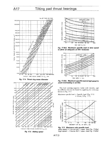
Fig. 17.6(a). Maximum specific load at slow speed
to allow an adequate oil film thickness
THRUST RING MEAN DIAMETER D,, mm
PAD SIZE b, rnm
Fig. 17.4. Thrust ring mean diameter
Fig. 17.6(b). Maximum specific load at high speed to
avoid overheating in oil film
The load carrying capacity varies with viscosity, and
for different oils may be found by applying the correction
factors in Fig. 17.7:
Maximum specific load = Specific load (Fig. 17.6)
X factory (Fig. 17.7).
40
n 30
a
20
1.0
0.8
06
04
03 (b)
6 6 10 20 40 60 EO 100
VISCOSITY OF OIL AT 6OoC, cSt
Fig. 17.7. Maximum safe specific load:
THRUST RING MEAN DIAMETER D,, rnrn slow speed = f (curve (a)) x spec. load Fig. 17.6(a)
Fig. 17.5. Sliding speed high speed = f (curve (b)) x spec. load Fig. 17.6(b)
A 17 '.3