Page 104 - The Tribology Handbook
P. 104

Hydrostatic bearings                                     A18


                    RELIEF  VALVE


                                                                                                            IO'O


                          L              1


                                  CONSTANT-FLOW VALVE
                                                                                                            109


                                                    BEARING
                                                                                                            IO*


                          L              I
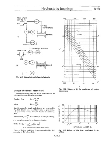
                   Fig. 18.4.  Layout of typical control circuits


                                                                                                            10'
                                                                                   I
                                                                       0.05       0.        0.2        04
                                                                                        d
                                                                  Fig.  18.5.  Values  of  K,  for  capillaries  of  various
                 Design of control restrictors                    dimensions
                  Dimensions of  capillary and  orifice  restrictors  may  be
                 calculated from the following equations
                                       P/. -Po
                 Capillary flow   Qo  = --
                                        Kc q
                                        I28 1
                 where            K =--                               0.8
                                    e   7rd4
                                                                  u'
                 Suitable values for length and diameter  are presented  in   0.7
                 Fig.  18.5. The I/d  ratio should preferably be greater  than
                 100 for accuracy and the Reynolds Number should be less   0.6
                than
                              PUd                                     0.5
                 1000 where Re =  -->   p  = density, v  = average velocity,
                               v                                      0.4
                d = bore diameter and q  = dynamic viscosity.
                                                                      a3
                                                                           4  8
                          A  = cross-sectional area of the orifice.                REYNOLDS  NUMBER  Re
                Values of the flow coefficient C,are  presented in Fig. 18.6   Fig.  18.6.  Values  of  the  flow  coefficient  C,  for
                according to the values of Re.                    orifices
                                                             AI 8.2
   99   100   101   102   103   104   105   106   107   108   109