
Page 107 - The Tribology Handbook
P. 107
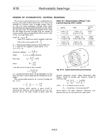
A18                           Hvdrostatic beari nas


                DESIGN  OF HYDROSTATIC  JOURNAL  BEARINGS
                  The geometry and nomenclature of a cylindrical journal   Table 18.1  Dimensionless stiffness  (for
                bearing with n pads are illustrated in Fig. 18.13. Forjournal   a journal bearing with n pads)
                bearings  the  optimum  value  of  design  pressure  ratio  is
                fi  = 0.5  as  for  other  hydrostatic  bearings.  Other  values                      Constant
                of fl will reduce the minimum film thickness and may reduce   Capillary   Orijice    Po.,
                the maximum load. The following equations form a basis
                for  safe  design  of journal  bearings  with  any  number  of   3.82 8 (1 -8)   7.658 (1 -8)   3.82 8
                                                                                                      -
                recesses and the three principal forms of flow control (refer   4   1+Y  (1-8)   2--8+2Y  (1-8)   1 +Y
                to Fig.  18.13 and Table  18.1).
                                                                       4.128 (1 -B)    8.25 8 (1 -8)   4.258
                Load : W = p r-Ae.
                     where Wis a load factor which normally varies from   5   1 +0.69 y (1 -8)   2-8-t  1.38Y (1 -8)   1 +0.69Y
                                               T                  -_   .
                     0.30 to 0.6  a better guide is   = -              4.30 8 (1 -8)   8.608 (1 -8)   4.308
                                                2                                    2-84-Y  (1-8)
                x  = dimensionless stiffness parameter from Table  18.1   6   1+0.5y(l-8)             1+0.5y
                2 = value of   for  capillary  control  and fi  = 0.5,
                A,  = D  (L-a).
                                     Pf 41
                Concentric stiffness:  A = -
                                       c
                where       C = h,  = radial clearance.

                Flow-rate :
                                   -   nD
                where             B=-
                                      6an
                is the flow factor for one of the n recesses.
                                    n a (L-a)                     Fig. 18.13.  Typical hydrostatic journal bearing
                                Y=
                                      nDb
                is a  ircumferential flow factor.  If the dimension ‘6’  is too
                small the value y will be large and the bearing will be un-   Previous  Paragraph  heded  ‘Plane  Hydrostatic  pad
                stable.                                           Design’.  Values  of  viscosity  and  clearance  should  be
                  The recommended geometry for a journal bearing  (see   selected  So  that:
                Fig.  18.13).
                               L   L          ZD                              Pr
                            a=- 4, _- D-l,   b=-
                                               4n                 where  X  = rotational speed in revlsec
                Journal  bearings  which  operate  at  speed  should  be   = [(total area) -3  (recess area)]/D2
                optimised  for  minimum  power  dissipation  and  low  tern-   R~~~~~ depth  = 20  radial  clearance.  ~~~i~~~   tem-
                perature  rise  for  the  same  reasons  as  given  under  the   perature  rise may be calculated as for plane  pads.


                                                            A18.5