
Page 110 - The Tribology Handbook
P. 110
Gas bearings A19
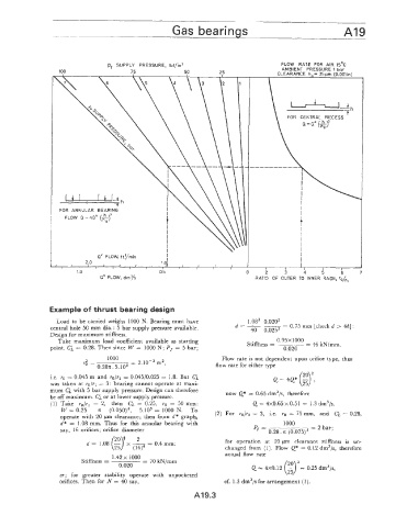
pr SUPPLY PRESSURE, Ibf/inz FLOW RATE FOR AIR 15’C
100 75 50 25
\
FOR ANNULAR BEARING
Q* FLOW, ftyrnin
,
1.0 0.5 0 2 3 4 5 b 7
Q* FLOW, dmys RATIO OF OUTER TO INNER RADII, r~/~,
Example of thrust bearing design
Load to be c:arried weighs 1000 N. Bearing must have 1.08’ 0.0202
--
central hole 50 mm dia. : 5 bar supply pressure available. d=- 40 0.0253 - 0.75 mm [check d > 4h]
Design for maximum stiffness.
Take maximum load coefficient available as starting 0.95~1000
= 46 kN/mm.
point. Ci = 0.28. Then since W = 1000 N; Pf = 5 bar; Stiffness = 0.020
1000 Flow rate is not dependent upon orifice type, thus
7; = = 2.10-~ m’, ffow rate for either type
0.28~. 5.105
Le. 70 = 0.045 m and ro/r1 = 0.045/0.025 = 1.8. But C; Q = 4Q* ($2,
was taken at ro/7l = 3: bearing cannot operate at maxi-
mum G;. with 5 bar supply pressure. Design can therefore now Q* = 0.65 dm3/s, therefore
be off maximum. C; or at lower supply pressure.
x
(1) Take ro/rl = 2, then C; = 0.25, 70 = 50 mm: Q = 4~0.65 0.51 = 1.3 dm3/s.
W = 0.25 n (0.050)’, 5.105 = 1000 N. TO (2) For 7o/r1 = 3, i.e. 70 = 75 mm, and C;, = 0.28,
operate with 20 pm Clearance; then from d* graph,
d* = 1.08 mm. Thus for this annular bearing with P- 1000
say, 16 orifices; orifice diameter ’ - 0.28. x (0.075)’ = 2 bar;
2 for operation at 20 pm clearance stiffness is un-
d = 1.08 (Eyx ~f = 0.4 mm:
changed from (1). Flow Q* = 0.12 dm3/s, therefore
actual flow rate
(::I3
1.42 x 1000
Stiffness = -- = 70 kN/mm
0.020 Q = 4~0.12 - = 0.25 dm3/s,
os; for greater stability operate with unpocketed
orifices. Then for N = 40 say, cf. 1.3 dm3/s for arrangement (1).
Al9.3