
Page 103 - The Tribology Handbook
P. 103
A18 Hydrostatic bearings
In a hydrostatic bearing the surfaces are separated by a film of lubricant supplied under pressure to one or more recesses
in the bearing surface. If the two bearing surfaces are made to approach each other under the influence of an applied load
the flow is forced through a smaller gap. This causes an increase in the recess pressure. The sum of the recess pressure and
the pressures across the lands surrounding the recess build up to balance the applied load. The ability of a bearing film to
resist variations in gap with load depends on the type of flow controller.
LOAD CAPACITY CONTROL CIRCUITS
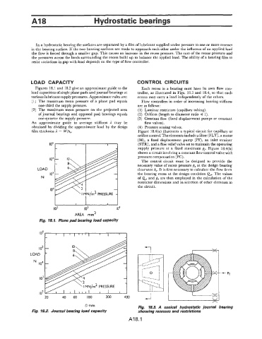
Figures 18.1 and 18.2 give an approximate guide to the Each recess in a bearing must have its own flow con-
load capacities of single plane pads and journal bearings at troller, as illustrated in Figs. 18.3 and 18.4, so that each
various lubricant supply pressures. Approximate rules are: recess may carry a load independently of the others.
(1) The maximum mean pressure of a plane pad equals Flow controllers in order of increasing bearing stiffness
one-third the supply pressure. are as follows :
(2) The maximum mean pressure on the projected area (1) Laminar restrictors (capillary tubing).
of journal bearings and opposed pad bearings equals (2) Orifices (length to diameter ratio 4 1).
one-quarter the supply pressure. (3) Constant flow (fixed displacement pumps or constant
An approximate guide to average stiffness 1 may be flow valves).
obtained by dividing the approximate load by the design (4) Pressure sensing valves.
film thickness il = W/ho. Figure 18.4(a) illustrates a typical circuit for capillary or
orifice control. The elements include a filter (FLT), a motor
(M), a fixed displacement pump (PF), an inlet strainer
(STR), and a flow relief valve set to maintain the operating
supply pressure at a fixed maximum &. Figure 18.4(b)
shows a circuit involving a constant flow control valve with
pressure compensation (PC) .
io4 The control circuit must be designed to provide the
necessary value of recess pressure po at the design bearing
LOAD clearmce h,. It is first necessary to calculate the flow frnm
io3 the bearing recess at the design condition Qo. The values
N of QD and po are then employed in the calculation of the
restrictor dimensions and in selection of other elements in
the circuit.
Id
I I I 1 I
IO2 to3 io4
AREA mm2
Fig. 18.1. Plane pad bearing load capacity
D mm Fig. 18.3. A conical hydrostatic journal bearing
Fig. 18.2. Journal bearing load capacity showing recesses and restrictions
A18.1