
Page 161 - The Tribology Handbook
P. 161
Belt drives B1
BELT TENSIONS
s mls
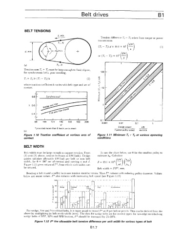
Tension difference T, - T, arises from torque or power
transmission
(k3
-
(T, - T,).d= 19.1 X lo6
-t
Tension sum TI + Tz must be large enough to limit slip or,
for synchronous belts, poor meshing. 100
z
Ti + Tz3 (Ti - T,)/A (2) -
Y
h"
where traction coefficient A varies with belt type and arc of +
contact. h' 10
1
I I ._ z
Synchronous" -
.-
I
1
L I
0.1
80 100 120 140 160 180 200 0,001 0.01 0.1 1
0"
"provided more than 6 teeth are in mesh Design power kW
(b) Fastest pulley speed rev/min
Figure 1-10 Traction coefficient at various arcs of Figure 1.11 Minimum TI + T2 at various operating
contact conditions
BELT WIDTH
Belt width must be large enough to support tension. From To use the chart below, use 6 for the smallest pulley to
(1) and (2) above, tension increases as kW/(ndA). Design estimate Ae. Calculate
guides tabulate allowable kWl(nd) per belt or mm belt F = 19.1 X IO6 (5)
width, for 6 == 180" arc of contact and varying n and d.
Figure 1. i 2 gives values of F*, from which such tables can
be created. Belt width = F/F*, mm.
Bending a belt round a pulley increases tension member strain. Thus F* reduces with reducing pulley diameter. Values
below are mean values. F* also reduces with increasing belt speed (see Figure 1.13)
Synchronous
For wedge, Vee and Vee-ribbed belts, it is more usual to record F* as N per belt or per rib. This can be derived from the
above by multiplying by belt or rib width (mm). The data for wedge belts are for covered types: for raw-edge moulded-cog
wedge belts of SPZ, SPA and SPB Section, F* should be increased by 25-30%.
Figiire 1.12 F* the allowable belt tension difference per unit width for various types of belt
B1.7