Page 164 - The Tribology Handbook
P. 164

61                                    Belt drives


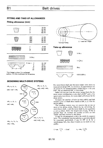
         FllTlNG AND TAKE-UP ALLOWANCES

         Fiiing allowance (mm)


                                 A            19-25
                                 E            25-40
                                 C            38-50
                                 0            50-75

                                 SPZ          12-20
                                 SPA          20-25
                                 SPB          25-30               I  l  l
                                 SPC          40-50             Take-up fitting       L = total belt length

                                 J             8-20       Take-up allowance
                                 L            22-30
                                 M            38-80
                                                                                    2-3% L

                                 2-3% L


                             P,mm  =  3       10-16'
                                     5        16-21
                                     8        24-35
                                    14        38-60
              L    P    J           20        49-80
        "For flanged pulleys. For unflanged
        pulleys, 2-5  mm issufficient for all sections
                                                                                    0.03-0.05% L


         DESIGNING MULTI-DRIVE SYSTEMS
                                                           For each driven shaft and the motor shaft, write down its
                                                           transmitted design kW, its rev/min R, its approximate arc
                                            = kW;  + kW3   of contact  8, its recommended  A  (from Figure  1.10) and
                                                           kW*, the accumulated kW, as illustrated.
                                                            Select belt section from the power rating charts for the
                                                           most severe combination at any shaft of kW* and n. For
                                                           speed reduction drives, the motor shaft will always be the
                                                           most severe.
                                                            Estimate the number of belts  (or belt width)  and belt
         kWl .nlI el, hl                                   tension as for a 2-shaft drive based on kW, n, d, A  for the
                                                           motor pulley.
         kW;  = kW1
                                                            The resulting  tension  may  not  prevent  slip on  one or
                                                           more of the driven  shafts.  Check this by  calculating,  for
                                                           each driven shaft, i, and the motor shaft m, the quantities
                                                          fi and fm below.  Select the largest ratio of fifm. If this is
                                                           greater  than  1.0, increase  the  number  of  belts  (or  belt
                                                           width) and belt tension  by  this factor.
                                                             It may be advantageous to drive the shafts by  separate
                                                           belts. The complexity may be such that a specialist should
                                                           be  consulted,  particularly  if  any  8 < 90" or  if,  for  a
         kW,  , n,  . em, hrn
                                                           synchronous belt,  less  than 6 teeth  are in  mesh  on any
         kWL = kW,                                         pulley.


                                                     91.10
   159   160   161   162   163   164   165   166   167   168   169