
Page 162 - The Tribology Handbook
P. 162
BI Belt drives
SHAFT LOADING
Static or installed shaft load
R = (TI + T2) sin (WZ)
Except for synchronous belts, (T, + 7'2) is obtained from
Figure 1.1 1. For synchronous belts, (T, + T2) is
50%-90% of value from Figure 1.11 increasing with
severity of shock loading: (T, + T,) rises to 100% during
power transmission.
Dynamic or running shaft load (1 + A2)
- (1 - X2)-
2
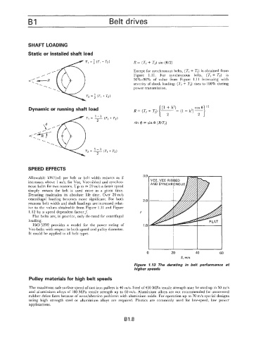
SPEED EFFECTS
Allowable kW/(nd) per belt or belt width reduces as S 3.0
increases above 1 m/s, for Vee, Vee-ribbed and synchro-
nous belts for two reasons. Up to = 20 m/s a faster speed
simply means the belt is used more in a given time.
Derating maintains its absolute life time. Over 20 m/s
centrifugal loading becomes more significant. For both 2.0
reasons belt width and shaft loadings are increased relat-
ive to the values obtainable from Figure 1.1 1 and Figure
1.12 by a speed dependent factor f. f
Flat belts are, in practice, only de-rated for centrifugal
loading.
IS0 5292 provides a model for the power rating of 1 .o
Vee-belts with respect to both speed and pulley diameter.
It could be applied to all belt types.
I I
0 20 40 60
S, rnls
Figure 1.13 The derating in belt performance at
higher speeds
Pulley materials for high belt speeds
The maximum safe surface speed of cast iron pulleys is 40 m/s. Steel of 430 MPa tensile strength may be used up to 50 m/s
and aluminium alloys of 180 MPa tensile strength up to 60 m/s. Aluminium alloys are not recommended for uncovered
rubber drive faces because of wear/abrasion problems with aluminium oxide. For operation up to 70 m/s special designs
using high strength steel or aluminium alloys are required. Plastics are commonly used for low-speed, low power
applications.
B1.8