Page 166 - The Tribology Handbook
P. 166

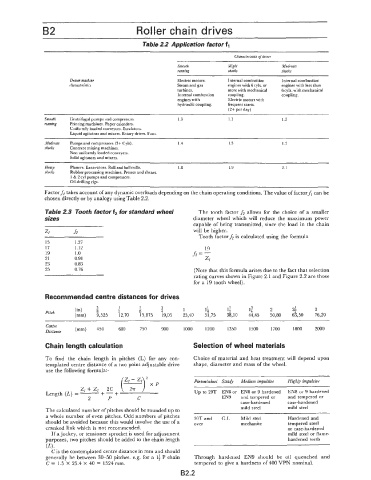
B2                             Roller chain drives

                                                Table 2.2 Application factor f,

                                                                               Characterisfics of driver
                                                            Smoofh           Slighf           Moderate
                                                            running          shocks           shocks
                        Driven machine                      Electric motors.   Internal combustion   Internal combustion
                        characferisfics                     Steam and gas    engines with 6 cyls. or   engines with less than
                                                            turbines.        more with mechanical   6 cyls. with mechanical
                                                            Internal combustion   coupling.   coupling.
                                                            engines with     Electric motors with
                                                            hydraulic coupling.   frequent starts.
                                                                             (2+ per day)
                Smooth   Centrifugal pumps and compressors.   I .o           1.1               1.3
                running   Printing machines. Paper calenders.
                        Uniformly loaded conveyors. Escalators.
                        Liquid agitators and mixers. Rotary driers. Fans.
                .Ifoderufe   Pumps and compressors (3+ Cyls)   I .4          1.5               1.7
                shocks   Concrete mixing machines.
                        Non uniformly loaded conveyers.
                        Solid agitators and mixers.
                Heaiy   Planers. Excavators. Roll and ball mills.   1.8      1.9               2.1
                shacks   Rubber processing machines. Presses and shears.
                        I  & 2 cy1 pumps and compressors.
                        Oil drilling rigs.
                Factorf,  takes account of any dynamic overloads depending on the chain operating conditions. The value of factorf,  can be
                chosen directly or by analogy using Table 2.2.

                Table 2.3  Tooth factor f2 for standard wheel      The tooth  factor f2 allows  for  the  choice  of  a  smaller
                sizes                                            diameter wheel  which  will  reduce  the  maximum  power
                                                                 capable of being transmitted,  since the load  in the chain
                                                                 will  be higher.
                                                                   Tooth factorh is calculated using the formula
                15        1.27
                17        1.12                                       19
                19        1  .o                                  h=-
                21        0.91                                       ZI
                23        0.83
                25        0.76                                   (Note that this formula arises due to the fact that selection
                                                                 rating curves shown in Figure 2.1 and Figure 2.2 are those
                                                                 for a  19 tooth wheel).

                Recommended centre distances for drives
                                 3       1     5       3      1      1;     1;      1;     2      2;     3
                                               -
                Pitch     (in)   s      2      8       4
                          (mm)   9,525   12,70   15,875   19,05   25,40   31,75   38,lO   44,45   50,80   63,50   76,20
                   ______   ~~______
                ~                      ~~
                Centre
                Drttance   (mm)   450   600     750    900    1000   1200    1350   1500   1700   1800    2000
                Chain length calculation                         Selection of wheel materials

                To  find  the  chain  length  in  pitches  (L)  for  any  con-   Choice of material  and heat  treatment  will  depend upon
                templated  centre distance of a  two point adjustable drive   shape, diameter and mass of the wheel.
                use the following formula:-
                                         (y)2                    Piniodwheel  Steady   Medium impulsive   Highhly impulsive

                            z, -+ z,   2c          x  P
                                   +
                                       +
                Length (I.) = -                                   Up to 29T  EN8 or  EN8 or 9 hardened   EN8 or 9 hardened
                                    -
                              2      P         C                           EN9   and tempered  or   and  tempered or
                                                                                 case-hardened   case-hardened
                The calculated number of pitches should be rounded up to         mild steel      mild steel
                a whole number of even pitches.  Odd numbers of pitches   30T and   C.I.   Mild steel   Hardened and
                should be avoided because this would involve the use of a   over   meehanite     tempered steel
                cranked link which is not recommended.                                           or case-hardened
                  If a jockey, or tensioner sprocket is used for adjustment                      mild  steel or flame-
                purposes, two pitches should be added to the chain length                        hardened teeth
                (L).
                  Cis the contemplated centre distance in mm and should
                generally be between 30-50  pitches.  e.g.  for a  1;  P chain   Through  hardened  EN9  should  be  oil  quenched  and
                C = 1.5 X  25.4 X  40 = 1524 mm.                  tempered  to give a hardness of 400 VPN nominal.
                                                             B2.2
   161   162   163   164   165   166   167   168   169   170   171