
Page 228 - The Tribology Handbook
P. 228
Wire ropes B13
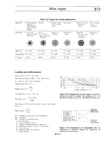
Table 13.2 Ropes for mining applications
~
Application Haulage (general), Winding Winding-drum Shaft guides Balance for drum Aerial carrying
conveyors, hoists, friction and friction ropes,
winding (small hoists hoists cableways
sizes), cableway
haulage
~~ ~~
Construclion 6 X 8(7/1)A 6 X 25 Locked coil- Locked coil- 'Superflex' Locked coil-
flattened strand 12/12/1 Br 9/3 winding guide 20 X 6/17 X 6/ aerial
160 Grade flattened Strand 13 X 6/6 X 19
180 Grade 110 Grade
MBL kN 8X 0.565 d X 0.613 8 X 0.851 8 X 0.500 8 X 0.368 d X 0.809
Wt kg/100 rn d X 0.407 d X 0.413 8 X 0.563 8 X 0.550 8 X 0.385 d X 0.568
~~ ~ ~~ ~ ~~ ~ ~~ ~~ ~~
E N/mrn2 61 800 58 800 98 100 117 700 53 900 117 700
Loading and performances
Static load (as) = Wc + W, + WR
Static factor of safeQ = MBL: 7: (Le. FOS = 6.5:l
J
for cranes etc. W, is not considered
Dynamic Load (TDJ = Ts . a
EAA
Bending load ( 'T8 J = -
D STRESS REVERSALS x IO6
Total load ( Tmaxj = Ts -+ T, + TB Figure 13.2 Fatigue tests on wire ropes la) flattened
strand, winding (b) locked coil, winding IC) 6 x 25
T,,, X 100 RS IWRC ordinary lay (d) 6 x 36 lWRC ordinary lay
Perceniage stre5.r =
MBL
(See Figure 13.2 for stress reversals based on percentage
stress.)
Ts . L OPTIMUM
Elastic stretch == __ ABRASION
EA RES I STA N CE
6 x 19 (9/9/1)
Wc = Weight of conveyance and attachments 17x7 (6/1)
W, = Payload 6x25 FS (12/12/4)
WB = Weight of suspended rope
a = Acceleration FATIGUE
g = Gravitational constant RESISTANCE
E = Elastic Modulus (based on rope area)
A = Diamet'er of rope at centre of outer wires
A = Area of rope Figure 13.3 Comparison of construction for (a)
D = Diameter of drum or sheave resistance to bending fatigue (b) resistance to
k = Rope length abrasion and crushing
B 13.2