Page 231 - The Tribology Handbook
P. 231

B15                              Damping devices


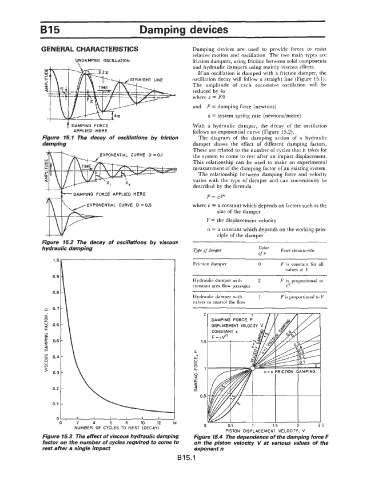
               GENERAL CHARACTERISTICS                           Damping  devices  are  used  to  provide  forces  to  resist
                                                                 relative  motion  and  oscillation.  The two  main  types are
                          UNDAMPED  OSCILLATION                  friction dampers, using friction between solid components
                           \
                                                                 and hydraulic dampers using mainly viscous effects.
                                                                   If an oscillation is damped with  a friction damper, the
                                                                 oscillation decay will follow a straight line  (Figure 15.1).
                                                                 The  amplitude  of  each  successive  oscillation  will  be
                                                                 reduced by  4x
                                                                 where x  = F/k
                                                                 and  F = damping force  (newtons)
                                                                      k = system spring rate (newtondmetre)

                  '    f  DAMPING  FORCE                         With  a  hydraulic  damper,  the  decay  of  the  oscillation
                         APPLIED  HERE                           follows an exponential curve (Figure 15.2).
               Figure  15.1  The  decay  of  oscillations by  friction   The  diagram  of  the  damping  action  of  a  hydraulic
               damping                                           damper  shows  the  effect  of  different  damping  factors.
                                                                 These are related to the number of cycles that it takes for
                                  EXPONENTIAL  CURVE  D = 0.1    the system to come to rest  after an impact displacement.
                                                                 This  relationship  can  be  used  to  make  an experimental
                                                                 measurement of the damping factor of an existing system.
                                                                   The relationship  between  damping force and  velocity
                                                                 varies  with  the  type of damper and can conveniently be
                                                                 described by the formula
                         DAMPING  FORCE, APPLIED  HERE
                                                                      F= CP
                              EXPONENTIAL  CURVE  D = 0.5        where c = a constant which depends on factors such as the
                                                                         size of the damper
                                                                      V = the displacement  velocity
                                                                      n = a constant which depends on the working prin-
                                                                         ciple of the damper
               Figure  15.2  The  decay  of  oscillations by  viscous
               hydraulic damping                                 Type of  damper       Value   Force characteristic
                                                                                       of n
                                                                 Friction damper       0      F  is  constant  for  all
                                                                                                values of  V
                                                                                ~~           ~   ~~   ~
                                                                 Hydraulic damper with   2    F  is  proportional  to
                                                                 constant area flow passages    V2
                                                                 Hydraulic damper with   1    F is proportional to V
                                                                 valves to control the flow
                                                                     2

                                                                             MEN1  VELOCIT

                                                                    1.5
                                                                 LL
                                                                  w'
                                                                  u
                                                                  a
                                                                  0
                                                                  LL1
                                                                  0
                                                                  z
                                                                  Q
                                                                  5
                                                                  U
                                                                  n
                                                                    0.5
                           I    I     I    I    I     I
                     0     2    4     6    8    10   12              0       0.5     1      1.5     2      2.5
                          NUMBER  OF  CYCLES  TO  REST  (DECAY)             PISTON  DISPLACEMENT  VELOCITY,  v
               Figure 15.3  The effect of viscous hydraulic damping   Figure 15.4  The dependence of the damping force F
               factor on the number of cycles required to come to   on  the piston  velocity  V at  various  values  of  the
               rest after a single impact                         exponent n
                                                            B15.1
   226   227   228   229   230   231   232   233   234   235   236