
Page 233 - The Tribology Handbook
P. 233
B15 Damping devices
POINTS TO NOTE IN DAMPER SELECTION AND DESIGN
1. Friction dampers can potentially absorb the most ener-
gy, but are unsuitable for systems subject to steady
oscillations at or near resonance, unless the friction
dampers are large enough to provide a damping force of
at least four times any excitation force.
2. To give satisfactory performance with acceptable wear
rates, the contact pressures in friction pad dampers
should not exceed 250 kN/m2 (34 p.s.i.).
3. With hydraulic dampers, damping factors in the range
0.25 to 0.4 are generally suitable, but at frequency
ratios above r = 2.5 the transmitted forces are higher
than with friction dampers.
4. With viscous hydraulic dampers giving straight line
force/velocity characteristics it is important to specify
the velocity at which the force should be Levelled to a
constant value by a cut-off valve. A valve of adequate
capacity is needed to prevent instantaneous velocity
peaks from bursting the housing or causing damage to
the working valves or the end mountings. The maxi-
mum allowable pressure at cut-off is usually of the
order of 3.5 MN/m2 (500 p.s.i.).
5. If damping devices are likely to be operated near the
resonant frequency of the system, the rigidity of the
rubber pads or mounting bushes need to be checked for
adequate stiffness.
u1
0 +
6
ti
w
0
rr
9
0
f
a
r
a
0
0 DAMPER VELOCITY V, m/5
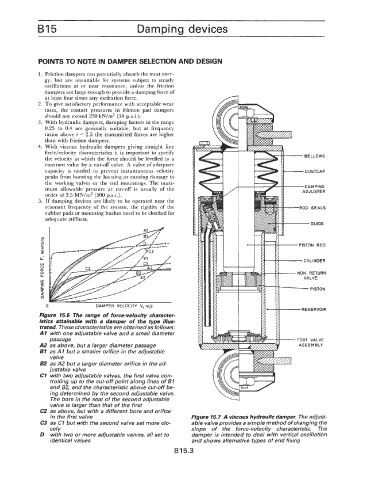
Figure 15.6 The range of force-velocity character-
istics attainable with a damper of the type illus-
trated. These characteristics are obtained as follows:
AI with one adjustable valve and a small diameter
passage
A2 as above, but a larger diameter passage
61 as AI but a smaller orifice in the adjustable
valve
62 as A2 but a larger diameter orifice in the ad-
justable valve
C7 with two adjustable valves, the first valve con-
trolling up to the cut-off point along lines of BI
and B2, and the characteristic above cut-off be-
ing determined by the second adjustable valve.
The bore in the seat of the second adjustable
valve is larger than that of the first
C2 as above, but with a different bore and orifice
in the first valve
C3 as CI but with the second valve set more clo-
sely
D with two or more adjustable valves, all set to
identical values
B 15.3