
Page 230 - The Tribology Handbook
P. 230
Control cables B14
Pulley size and cable fatigue Friction in Bowden cables
The friction of wires and cables inside conduits (Bowden
cables) depends on the materials and construction of the
cable and conduit and on the bend radii obtained when
the system is installed. Control runs employing flexible
conduit should take a natural path between the conduit
grounding points.
The materials used may be:
Metal cable in a metal conduit with grease lubrication.
Metal cable in a plastic lined conduit.
i Plastic coated metal cable in a conduit lined with a
dissimilar plastic.
The last combination gives low friction and high effi-
Figure 14. I ,PuYley groove form for control ciency compared with the first, as shown in the figure
purposes. Groove radius R = 0.53d where d = cable below.
diameter inclusive of any thermoplastic covering
INPUT LOAD Lbf
Although Bowden cables were conceived to eliminate the 100 200 300 400 500 600 700
90 I
I
1
use of ropes and pulleys, control configurations using steel 5 861 /c 1 1
wire ropes and pulleys are in use.
For very simal1 rope below 2 mm diameter, pulley
diameter (over groove) should not be less than thirty times LL z? "PLASTIC ON PLASTIC
rope diameter. For small rope used as controls (2 to 6 mm
diameter), pulley diameter over groove should not be less
than thirty-five times actual rope diameter (exclude the
effect of any plastic covering). Nylon or acetal moulded
pulleys give excellent life, resist corrosion and reduce
friction and w'ear between rope and pulley. Prediction of
fatigue life of r,opes around pulleys is difficult and involves
many factors. ]Practical tests have shown that provided the
minimum recommended pulley diameters are used and
that the tension load in the rope does not exceed 10% of
the minimum breaking load of the rope, long life can be
expected. Angles of wrap between 10" and 30" should be
avoided; reverse bends should be avoided wherever 621 1 I I I
possible. 0 400 800 1200 1600 2000 2400 2800 3200
The following table shows the effect on fatigue life with INPUT LOAD M
varying
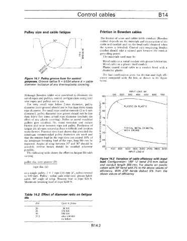
Figure 14.2 Variation of cable efficiency with input
Dullev dia. over eroove (D) load, Configuration: 180" 'U' bend 210 mm radius
and conduit length 800 mm. For plastic on plastic
-~ ~~
rope dia. (d) cables with 90" bend add 2% to the above values of
efficiency. With 270" bends deduct 5% from the
on a single pulley. 7 X 7 rope 2.60 mm (d), nylon covered above values of efficiency
PO 3.60 mm. Pulley-nylon; axle mild steel, grease lubri-
cated. 90" angle of wrap. Tension load in rope 625 N.
Minimum breaking load of rope 6250 N.
Table 14.2 Effect of diameter ratio on fatigue
life
D/d Cycles to failure
20 56 000
25 170 000
30 330 000
37.5 after 650 000
no failure
B 14.2