
Page 1148 - The Mechatronics Handbook
P. 1148
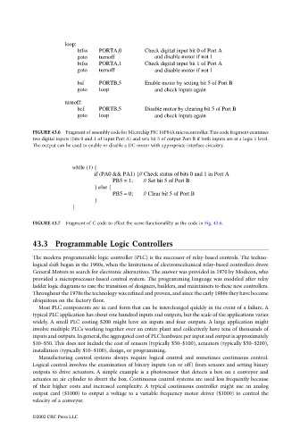
loop:
                                                btfss   PORTA,0        Check digital input bit 0 of Port A
                                                goto    turnoff               and disable motor if not 1
                                                btfss   PORTA,1        Check digital input bit 1 of Port A
                                                goto    turnoff               and disable motor if not 1

                                                bsf     PORTB,5        Enable motor by setting bit 5 of Port B
                                                goto    loop                  and check inputs again

                                            turnoff:
                                                bcf     PORTB,5        Disable motor by clearing bit 5 of Port B
                                                goto    loop                  and check inputs again

                                 FIGURE 43.6  Fragment of assembly code for Microchip PIC 16F84A microcontroller. This code fragment examines
                                 two digital inputs (bits 0 and 1 of input Port A) and sets bit 5 of output Port B if both inputs are at a logic 1 level.
                                 The output can be used to enable or disable a DC motor with appropriate interface circuitry.


                                               while (1) {
                                                      if (PA0 && PA1) {// Check status of bits 0 and 1 in Port A
                                                            PB5 = 1;       // Set bit 5 of Port B
                                                      } else {
                                                            PB5 = 0;       // Clear bit 5 of Port B
                                                      }
                                               }

                                 FIGURE 43.7  Fragment of C code to effect the same functionalilty as the code in Fig. 43.6.


                                 43.3 Programmable Logic Controllers


                                 The modern programmable logic controller (PLC) is the successor of relay-based controls. The techno-
                                 logical shift began in the 1960s, when the limitations of electromechanical relay-based controllers drove
                                 General Motors to search for electronic alternatives. The answer was provided in 1970 by Modicon, who
                                 provided a microprocessor-based control system. The programming language was modeled after relay
                                 ladder logic diagrams to ease the transition of designers, builders, and maintainers to these new controllers.
                                 Throughout the 1970s the technology was refined and proven, and since the early 1980s they have become
                                 ubiquitous on the factory floor.
                                   Most PLC components are in card form that can be interchanged quickly in the event of a failure. A
                                 typical PLC application has about one hundred inputs and outputs, but the scale of the applications varies
                                 widely. A small PLC costing $200 might have six inputs and four outputs. A large application might
                                 involve multiple PLCs working together over an entire plant and collectively have tens of thousands of
                                 inputs and outputs. In general, the aggregated cost of PLC hardware per input and output is approximately
                                 $10–$50. This does not include the cost of sensors (typically $50–$100), actuators (typically $50–$200),
                                 installation (typically $10–$100), design, or programming.
                                   Manufacturing control systems always require logical control and sometimes continuous control.
                                 Logical control involves the examination of binary inputs (on or off) from sensors and setting binary
                                 outputs to drive actuators. A simple example is a photosensor that detects a box on a conveyor and
                                 actuates an air cylinder to divert the box. Continuous control systems are used less frequently because
                                 of their higher costs and increased complexity. A typical continuous controller might use an analog
                                 output card ($1000) to output a voltage to a variable frequency motor driver ($1000) to control the
                                 velocity of a conveyor.

                                 ©2002 CRC Press LLC