
Page 1152 - The Mechatronics Handbook
P. 1152
start
S1 R in_valve1
power R in_valve2
empty1 & empty2 not(empty1 & empty2)
S2 S run_light S3 S out_valves
R out_valves
empty1 & empty2
S4 S run_light
R out_valves
run
S5 S in_valve1 S6 S in_valve2
not(empty1) not(empty2)
S7 R in_valve1 S8 R in_valve2
S9 S out_valves
empty1 & empty2
S10 R out_valves
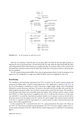
FIGURE 43.12 An SFC program for tank level control.
After the run transition is fired the flow of execution splits into both the left and right branches, as
indicated by the two horizontal lines. The left branch fills one tank, while the right branch fills the other
tank independently. When both branches are complete the flow of execution rejoins at the second set of
horizontal lines, and then activates step S9. After step S10 the flow of execution returns to the point after
the run transition.
The SFC programming method differs from other programming methods in that the program is not
expected to run completely in a single scan, while all others must run completely in each scan.
Interfacing
The installation and interfacing requirements for PLCs are driven by the need to protect people and
equipment by failing safely. A typical wiring diagram for a PLC application is shown in Fig. 43.13. At
the top of the diagram a transformer is used to step down a higher supply voltage. This is immediately
followed by a power disconnect and fuses. The power is then split into left and right rails, much like the
ladder diagrams discussed earlier. Line 10 shows a master power control for the system. This includes a
normally open start button and a normally closed stop button. These switches control a master control
relay (MCR) C1. Notice that if power is supplied to the coil C1, it will close the contacts C1 on the same
run and hold C1 on until the stop button is pushed. Another set of contacts is used on the left rail to
disconnect power from the inputs to the PLC and the DC power supply. This control circuitry external
to the PLC is required so that the stop buttons of a control system are able to directly disconnect the
power. This is often required by law.
In this example the PLC is powered with 120 V AC, connected between the power rails. There are
two 120 V AC inputs from normally open push buttons. The 24 V DC power supply is input to the V+
on the output terminals of the PLC, which will then switch output power to solenoid S1 and indicator
light L1.
©2002 CRC Press LLC