
Page 1149 - The Mechatronics Handbook
P. 1149
LADDER LOGIC BOOLEAN
EQUATIONS
A D X
X = (A + B . C) . D
B C
X A Y
Y = X . (A + D)
D
hot neutral
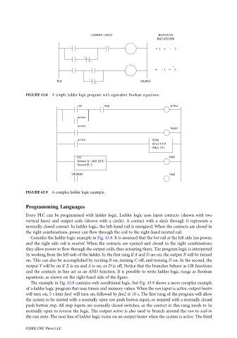
FIGURE 43.8 A simple ladder logic program with equivalent Boolean equations.
run stop active
active
active
heater
active TON
timer T4:0
delay 10 s
GT fan1
Source A: T4:0.ACC
Source B: 5
T4:0/DN fan2
FIGURE 43.9 A complex ladder logic example.
Programming Languages
Every PLC can be programmed with ladder logic. Ladder logic uses input contacts (shown with two
vertical lines) and output coils (shown with a circle). A contact with a slash through it represents a
normally closed contact. In ladder logic, the left-hand rail is energized. When the contacts are closed in
the right combinations, power can flow through the coil to the right-hand neutral rail.
Consider the ladder logic example in Fig. 43.8. It is assumed that the hot rail at the left side has power,
and the right side rail is neutral. When the contacts are opened and closed in the right combinations
they allow power to flow through the output coils, thus actuating them. The program logic is interpreted
by working from the left side of the ladder. In the first rung if A and D are on, the output X will be turned
on. This can also be accomplished by turning B on, turning C off, and turning D on. In the second, the
output Y will be on if X is on and A is on, or D is off. Notice that the branches behave as OR functions
and the contacts in line act as an AND function. It is possible to write ladder logic rungs as Boolean
equations, as shown on the right-hand side of the figure.
The example in Fig. 43.8 contains only conditional logic, but Fig. 43.9 shows a more complex example
of a ladder logic program that uses timers and memory values. When the run input is active, output heater
will turn on, 5 s later fan1 will turn on, followed by fan2 at 10 s. The first rung of the program will allow
the system to be started with a normally open run push button input, or stopped with a normally closed
push button stop. All stop inputs are normally closed switches, so the contact in this rung needs to be
normally open to reverse the logic. The output active is also used to branch around the run to seal-in
the run state. The next line of ladder logic turns on an output heater when the system is active. The third
©2002 CRC Press LLC