
Page 1150 - The Mechatronics Handbook
P. 1150
line will run a timer when active is on. When the input to the TON timer goes on, the timer T4:0 will
begin counting, and the timer element T4:0.ACC will begin to increment until the delay value of 10 s is
reached, at this point the timer done bit T4:0/DN bit will turn on and stay on until the input to the timer
is turned off. The fourth rung will compare the accumulated time of the timer and if it is greater than
5 the output fan1 will be turned on. The final rung of the program will turn on fan2 after the timer has
delayed 10 s.
A PLC scans (executes) a ladder logic program many times per second. Typical execution times range
from 5 to 100 ms. Faster execution times are required for processes operating at a higher speed.
The notations and function formats used in Fig. 43.9 are based on those developed by a PLC manu-
facturer. In actuality, every vendor has developed a different version of ladder logic.
IEC 61131-3 Programming Languages
The IEC 61131 standards (formerly IEC 1131) have been created to unify PLCs [3,5]. The major portions
of the standard are listed below.
IEC 61131-1 Overview
IEC 61131-2 Requirements and Test Procedures
IEC 61131-3 Data Types and Programming
IEC 61131-4 User Guidelines
IEC 61131-5 Communications
IEC 61131-7 Fuzzy Control
The most popular part of the standard is the programming specification, IEC 61131-3. It describes five
basic programming models including ladder diagrams (LD), instruction list (IL), structured text (ST),
sequential function charts (SFC), and function block diagrams (FBD). These languages have been designed
to work together. It is possible to implement a system using a combination of the languages, or to
implement the same function in different languages. A discussion of ST, SFC, and FDB programs follows.
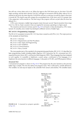
Structured Text
A structured text program is shown in Fig. 43.10. This program has the same function as the previous
ladder logic example. The first line defines the program name. This is followed by variable definitions.
The variables run and stop are inputs to the controller from sensors and switches. The variables heater,
PROGRAM example
VAR_INPUT
run : BOOL ;
stop : BOOL ;
END_VAR
VAR_OUTPUT
heater : BOOL ;
fan1 : BOOL ;
fan2 : BOOL ;
END_VAR
VAR
active : BOOL ;
delay : TON ;
END_VAR
active := (run OR active) & stop ;
heater := active ;
delay(EN := active, PRE := 10) ;
IF ( delay.ACC > 5 ) THEN
fan1 := 1 ;
ELSE fan1 := 0 ;
END_IF ;
FIGURE 43.10 A structured text program equivalent fan2 := delay.DN ;
to Fig. 43.9. END_PROGRAM
©2002 CRC Press LLC