
Page 1151 - The Mechatronics Handbook
P. 1151
run
OR
active
active
AND
stop
heater
TON
EN DN fan2
10 PRE ACC A
A > B fan1
5 B
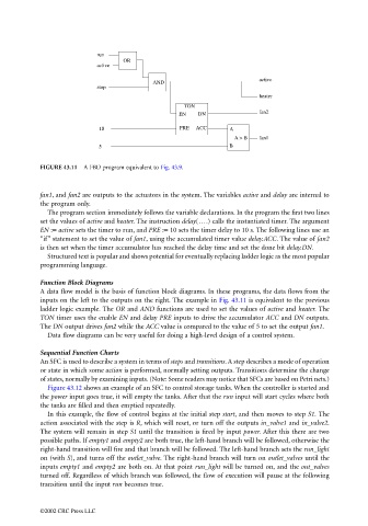
FIGURE 43.11 A FBD program equivalent to Fig. 43.9.
fan1, and fan2 are outputs to the actuators in the system. The variables active and delay are internal to
the program only.
The program section immediately follows the variable declarations. In the program the first two lines
set the values of active and heater. The instruction delay(….) calls the instantiated timer. The argument
EN := active sets the timer to run, and PRE := 10 sets the timer delay to 10 s. The following lines use an
“if” statement to set the value of fan1, using the accumulated timer value delay.ACC. The value of fan2
is then set when the timer accumulator has reached the delay time and set the done bit delay.DN.
Structured text is popular and shows potential for eventually replacing ladder logic as the most popular
programming language.
Function Block Diagrams
A data flow model is the basis of function block diagrams. In these programs, the data flows from the
inputs on the left to the outputs on the right. The example in Fig. 43.11 is equivalent to the previous
ladder logic example. The OR and AND functions are used to set the values of active and heater. The
TON timer uses the enable EN and delay PRE inputs to drive the accumulator ACC and DN outputs.
The DN output drives fan2 while the ACC value is compared to the value of 5 to set the output fan1.
Data flow diagrams can be very useful for doing a high-level design of a control system.
Sequential Function Charts
An SFC is used to describe a system in terms of steps and transitions. A step describes a mode of operation
or state in which some action is performed, normally setting outputs. Transitions determine the change
of states, normally by examining inputs. (Note: Some readers may notice that SFCs are based on Petri nets.)
Figure 43.12 shows an example of an SFC to control storage tanks. When the controller is started and
the power input goes true, it will empty the tanks. After that the run input will start cycles where both
the tanks are filled and then emptied repeatedly.
In this example, the flow of control begins at the initial step start, and then moves to step S1. The
action associated with the step is R, which will reset, or turn off the outputs in_valve1 and in_valve2.
The system will remain in step S1 until the transition is fired by input power. After this there are two
possible paths. If empty1 and empty2 are both true, the left-hand branch will be followed, otherwise the
right-hand transition will fire and that branch will be followed. The left-hand branch sets the run_light
on (with S), and turns off the outlet_valve. The right-hand branch will turn on outlet_valves until the
inputs empty1 and empty2 are both on. At that point run_light will be turned on, and the out_valves
turned off. Regardless of which branch was followed, the flow of execution will pause at the following
transition until the input run becomes true.
©2002 CRC Press LLC