
Page 1189 - The Mechatronics Handbook
P. 1189
n–1
FIGURE 46.1 Flash ADC—A flash converter has 2 comparators operating in parallel. It relies on the uniformity
of the resistors for linearity.
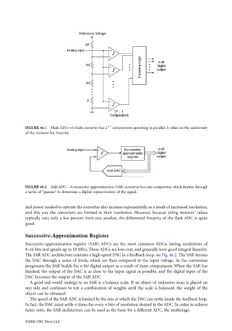
FIGURE 46.2 SAR ADC—A successive-approximation (SAR) converter has one comparator, which iterates through
a series of “guesses” to determine a digital representation of the signal.
and power needed to operate the converter also increase exponentially as a result of increased resolution,
and this way the converters are limited in their resolution. However, because string resistors’ values
typically vary only a few percent from one another, the differential linearity of the flash ADC is quite
good.
Successive-Approximation Register
Successive-approximation register (SAR) ADCs are the most common ADCs, having resolutions of
8–16 bits and speeds up to 10 MS/s. These ADCs are low-cost, and generally have good integral linearity.
The SAR ADC architecture contains a high-speed DAC in a feedback loop, see Fig. 46.2. The SAR iterates
the DAC through a series of levels, which are then compared to the input voltage. As the conversion
progresses, the SAR builds the n-bit digital output as a result of these comparisons. When the SAR has
finished, the output of the DAC is as close to the input signal as possible, and the digital input of the
DAC becomes the output of the SAR ADC.
A good real world analogy to an SAR is a balance scale. If an object of unknown mass is placed on
one side and continues to test a combination of weights until the scale is balanced, the weight of the
object can be obtained.
The speed of the SAR ADC is limited by the rate at which the DAC can settle inside the feedback loop.
In fact, the DAC must settle n times for every n bits of resolution desired in the ADC. In order to achieve
faster rates, the SAR architecture can be used as the basis for a different ADC, the multistage.
©2002 CRC Press LLC