
Page 349 - The Mechatronics Handbook
P. 349
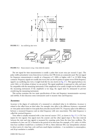
FIGURE 17.1  An oscillating sine wave.


                                 FIGURE 17.2  Measurement using a time interval counter.

                                   The test signal for time measurements is usually a pulse that occurs once per second (1 pps). The
                                 pulse width and polarity varies from device to device, but TTL levels are commonly used. The test signal
                                 for frequency measurements is usually at a frequency of 1 MHz or higher, with 5 or 10 MHz being
                                 common. Frequency signals are usually sine waves, but can also be pulses or square waves. If the frequency
                                 signal is an oscillating sine wave, it might look like the one shown in Fig. 17.1. This signal produces one
                                 cycle (360∞ or 2π radians of phase) in one period. The signal amplitude is expressed in volts, and must
                                 be compatible with the measuring instrument. If the amplitude is too small, it might not be able to drive
                                 the measuring instrument. If the amplitude is too large, the signal must be attenuated to prevent
                                 overdriving the measuring instrument.
                                   This section examines the two main specifications of time and frequency measurements—accuracy
                                 and stability. It also discusses some instruments used to measure time and frequency.

                                 Accuracy
                                 Accuracy is the degree of conformity of a measured or calculated value to its definition. Accuracy is
                                 related to the offset from an ideal value. For example, time offset is the difference between a measured
                                 on-time pulse and an ideal on-time pulse that coincides exactly with UTC. Frequency offset is the difference
                                 between a measured frequency and an ideal frequency with zero uncertainty. This ideal frequency is
                                 called the nominal frequency.
                                   Time offset is usually measured with a time interval counter (TIC), as shown in Fig. 17.2. A TIC has
                                 inputs for two signals. One signal starts the counter and the other signal stops it. The time interval
                                 between the start and stop signals is measured by counting cycles from the time base oscillator. The
                                 resolution of a low cost TIC is limited to the period of its time base. For example, a TIC with a 10-MHz
                                 time base oscillator would have a resolution of 100 ns. More elaborate TICs use interpolation schemes
                                 to detect parts of a time base cycle and have much higher resolution—1 ns resolution is commonplace,
                                 and 20 ps resolution is available.

                                 ©2002 CRC Press LLC