
Page 512 - The Mechatronics Handbook
P. 512
0066_frame_C19 Page 134 Wednesday, January 9, 2002 5:32 PM
output amplifier by a set of switches connected to the horizontal shitch register. Using two separate
vertical shift registers and separating row select and row reset functions enables a rolling curtain type of
electronic shutter to be implemented with an exposure ratio equal to the number of rows.
Photodiode arrays generally have less extensive electrode structures over each sensing element compared
with CCD arrays and consequently the spectral response is smoother and extends further at the blue end
of the spectrum, which is an advantage for color sensors. The peak quantum efficiency is also higher
ranging from 60% to 80% compared with 10% to 60% for photogates, leading to almost twice the electrical
output power for a given light input power. On the other hand, photodiodes have higher noise levels than
CCDs because of the reverse-bias leakage current. The photodiode can be operated in integrating mode
or in continuous mode. In the former, the photodiode capacitance is reset to a reference reverse bias and
then allowed to float. The charge on the photodiode capacitance is then discharged by photon-generated
current and leakage currents. After a specified integration time, the remaining charge can be read and the
difference from the reference value is proportional to the diode irradiance if the leakage sources are
negligible. Both passive and active pixel devices have been developed. In the latter, the charge on the photo-
diode is read out through a MOS field effect transistor (MOSFET), which converts charge to voltage and
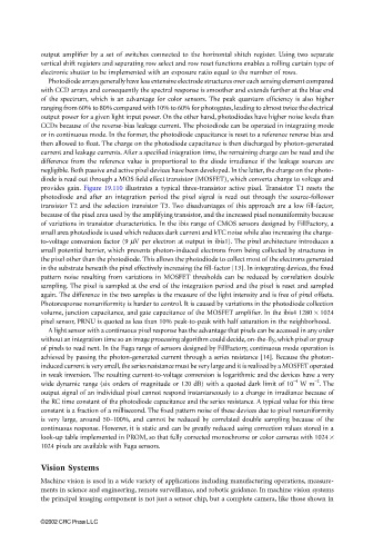
provides gain. Figure 19.110 illustrates a typical three-transistor active pixel. Transistor T1 resets the
photodiode and after an integration period the pixel signal is read out through the source-follower
transistor T2 and the selection transistor T3. Two disadvantages of this approach are a low fill-factor,
because of the pixel area used by the amplifying transistor, and the increased pixel nonuniformity because
of variations in transistor characteristics. In the ibis range of CMOS sensors designed by FillFactory, a
small area photodiode is used which reduces dark current and kTC noise while also increasing the charge-
to-voltage conversion factor (9 µV per electron at output in ibis1). The pixel architecture introduces a
small potential barrier, which prevents photon-induced electrons from being collected by structures in
the pixel other than the photodiode. This allows the photodiode to collect most of the electrons generated
in the substrate beneath the pixel effectively increasing the fill-factor [13]. In integrating devices, the fixed
pattern noise resulting from variations in MOSFET thresholds can be reduced by correlation double
sampling. The pixel is sampled at the end of the integration period and the pixel is reset and sampled
again. The difference in the two samples is the measure of the light intensity and is free of pixel offsets.
Photoresponse nonuniformity is harder to control. It is caused by variations in the photodiode collection
volume, junction capacitance, and gate capacitance of the MOSFET amplifier. In the ibis4 1280 × 1024
pixel sensor, PRNU is quoted as less than 10% peak-to-peak with half saturation in the neighborhood.
A light sensor with a continuous pixel response has the advantage that pixels can be accessed in any order
without an integration time so an image processing algorithm could decide, on-the-fly, which pixel or group
of pixels to read next. In the Fuga range of sensors designed by FillFactory, continuous mode operation is
achieved by passing the photon-generated current through a series resistance [14]. Because the photon-
induced current is very small, the series resistance must be very large and it is realized by a MOSFET operated
in weak inversion. The resulting current-to-voltage conversion is logarithmic and the devices have a very
−4
−2
wide dynamic range (six orders of magnitude or 120 dB) with a quoted dark limit of 10 W m . The
output signal of an individual pixel cannot respond instantaneously to a change in irradiance because of
the RC time constant of the photodiode capacitance and the series resistance. A typical value for this time
constant is a fraction of a millisecond. The fixed pattern noise of these devices due to pixel nonuniformity
is very large, around 50–100%, and cannot be reduced by correlated double sampling because of the
continuous response. However, it is static and can be greatly reduced using correction values stored in a
look-up table implemented in PROM, so that fully corrected monochrome or color cameras with 1024 ×
1024 pixels are available with Fuga sensors.
Vision Systems
Machine vision is used in a wide variety of applications including manufacturing operations, measure-
ments in science and engineering, remote surveillance, and robotic guidance. In machine vision systems
the principal imaging component is not just a sensor chip, but a complete camera, like those shown in
©2002 CRC Press LLC