
Page 594 - The Mechatronics Handbook
P. 594
0066_Frame_C20 Page 64 Wednesday, January 9, 2002 5:49 PM
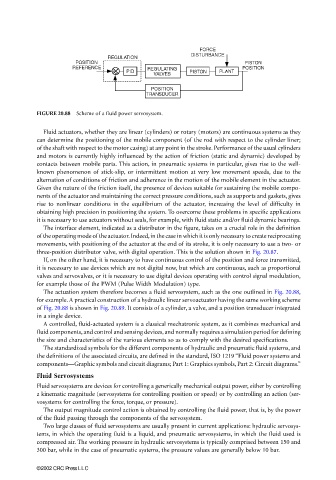
FIGURE 20.88 Scheme of a fluid power servosystem.
Fluid actuators, whether they are linear (cylinders) or rotary (motors) are continuous systems as they
can determine the positioning of the mobile component (of the rod with respect to the cylinder liner;
of the shaft with respect to the motor casing) at any point in the stroke. Performance of the usual cylinders
and motors is currently highly influenced by the action of friction (static and dynamic) developed by
contacts between mobile parts. This action, in pneumatic systems in particular, gives rise to the well-
known phenomenon of stick-slip, or intermittent motion at very low movement speeds, due to the
alternation of conditions of friction and adherence in the motion of the mobile element in the actuator.
Given the nature of the friction itself, the presence of devices suitable for sustaining the mobile compo-
nents of the actuator and maintaining the correct pressure conditions, such as supports and gaskets, gives
rise to nonlinear conditions in the equilibrium of the actuator, increasing the level of difficulty in
obtaining high precision in positioning the system. To overcome these problems in specific applications
it is necessary to use actuators without seals, for example, with fluid static and/or fluid dynamic bearings.
The interface element, indicated as a distributor in the figure, takes on a crucial role in the definition
of the operating mode of the actuator. Indeed, in the case in which it is only necessary to create reciprocating
movements, with positioning of the actuator at the end of its stroke, it is only necessary to use a two- or
three-position distributor valve, with digital operation. This is the solution shown in Fig. 20.87.
If, on the other hand, it is necessary to have continuous control of the position and force transmitted,
it is necessary to use devices which are not digital now, but which are continuous, such as proportional
valves and servovalves, or it is necessary to use digital devices operating with control signal modulation,
for example those of the PWM (Pulse Width Modulation) type.
The actuation system therefore becomes a fluid servosystem, such as the one outlined in Fig. 20.88,
for example. A practical construction of a hydraulic linear servoactuator having the same working scheme
of Fig. 20.88 is shown in Fig. 20.89. It consists of a cylinder, a valve, and a position transducer integrated
in a single device.
A controlled, fluid-actuated system is a classical mechatronic system, as it combines mechanical and
fluid components, and control and sensing devices, and normally requires a simulation period for defining
the size and characteristics of the various elements so as to comply with the desired specifications.
The standardized symbols for the different components of hydraulic and pneumatic fluid systems, and
the definitions of the associated circuits, are defined in the standard, ISO 1219 “Fluid power systems and
components—Graphic symbols and circuit diagrams; Part 1: Graphics symbols, Part 2: Circuit diagrams.”
Fluid Servosystems
Fluid servosystems are devices for controlling a generically mechanical output power, either by controlling
a kinematic magnitude (servosystems for controlling position or speed) or by controlling an action (ser-
vosystems for controlling the force, torque, or pressure).
The output magnitude control action is obtained by controlling the fluid power, that is, by the power
of the fluid passing through the components of the servosystem.
Two large classes of fluid servosystems are usually present in current applications: hydraulic servosys-
tems, in which the operating fluid is a liquid, and pneumatic servosystems, in which the fluid used is
compressed air. The working pressure in hydraulic servosystems is typically comprised between 150 and
300 bar, while in the case of pneumatic systems, the pressure values are generally below 10 bar.
©2002 CRC Press LLC