
Page 593 - The Mechatronics Handbook
P. 593
0066_Frame_C20 Page 63 Wednesday, January 9, 2002 5:49 PM
Continuous control of a force or of a speed can be effectively realized with a fluid actuation device,
with evident advantages compared with electric actuation, such as the possibility of maintaining the
system under load without any limitation and with the aid of adequate control devices, the possibility
of carrying out linear movements directly at high speeds, without devices for transforming rotary motion
to linear, and the possibility of having high bandwidths, in particular in hydraulic systems, as these have
limited dimensions and therefore low inertia.
Fluid Actuation Systems
An actuation system, which is part of an automatic machine, consists of a power part and a control part
as illustrated in Fig. 20.86. The power part comprises all the devices for effecting the movements or
actions. The control part provides for the processing of the information and generates the automated
cycle and the laws of variation of the reference signals, in accordance with the governing procedures
implemented and with the enabling and feedback signals arriving from the sensors deployed on the
operative part. The order signals coming from the control part are sent to the operative part by means
of the interface devices which convert and amplify the signals, where necessary, so that they can be used
directly by the actuators. These interfaces can be the speed drives or the contactors of the electric motors,
the distributor valves in hydraulic and pneumatic actuators.
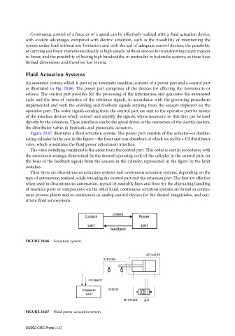
Figure 20.87 illustrates a fluid actuation system. The power part consists of the actuator—a double-
acting cylinder in the case in the figure—the front and rear chambers of which are fed by a 4/2 distributor
valve, which constitutes the fluid power adjustment interface.
The valve switching command is the order from the control part. This order is sent in accordance with
the movement strategy, determined by the desired operating cycle of the cylinder in the control part, on
the basis of the feedback signals from the sensors in the cylinder, represented in the figure by the limit
switches.
Then there are discontinuous actuation systems and continuous actuation systems, depending on the
type of automation realized, while retaining the control part and the actuation part. The first are effective
when used in discontinuous automation, typical of assembly lines and lines for the alternating handling
of machine parts or components; on the other hand, continuous actuation systems are found in contin-
uous process plants and as continuous or analog control devices for the desired magnitudes, and con-
stitute fluid servosystems.
FIGURE 20.86 Actuation system.
FIGURE 20.87 Fluid power actuation system.
©2002 CRC Press LLC