
Page 591 - The Mechatronics Handbook
P. 591
0066_Frame_C20 Page 61 Wednesday, January 9, 2002 5:49 PM
X
3
2 j x
Piezoelectric 1
transducer
4 5 6
x Shaft
7 8 9
(a)
Inductive
Outer transducer
ring
R b
w
h 1
dy
Piezoelectric
dz
transducer
(b)
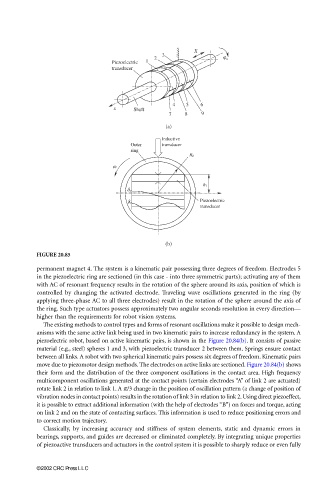
FIGURE 20.85
permanent magnet 4. The system is a kinematic pair possessing three degrees of freedom. Electrodes 5
in the piezoelectric ring are sectioned (in this case - into three symmetric parts); activating any of them
with AC of resonant frequency results in the rotation of the sphere around its axis, position of which is
controlled by changing the activated electrode. Traveling wave oscillations generated in the ring (by
applying three-phase AC to all three electrodes) result in the rotation of the sphere around the axis of
the ring. Such type actuators possess approximately two angular seconds resolution in every direction––
higher than the requirements for robot vision systems.
The existing methods to control types and forms of resonant oscillations make it possible to design mech-
anisms with the same active link being used in two kinematic pairs to increase redundancy in the system. A
piezoelectric robot, based on active kinematic pairs, is shown in the Figure 20.84(b). It consists of passive
material (e.g., steel) spheres 1 and 3, with piezoelectric transducer 2 between them. Springs ensure contact
between all links. A robot with two spherical kinematic pairs possess six degrees of freedom. Kinematic pairs
move due to piezomotor design methods. The electrodes on active links are sectioned. Figure 20.84(b) shows
their form and the distribution of the three component oscillations in the contact area. High frequency
multicomponent oscillations generated at the contact points (certain electrodes “A” of link 2 are actuated)
rotate link 2 in relation to link 1. A π/3 change in the position of oscillation pattern (a change of position of
vibration nodes in contact points) results in the rotation of link 3 in relation to link 2. Using direct piezoeffect,
it is possible to extract additional information (with the help of electrodes “B”) on forces and torque, acting
on link 2 and on the state of contacting surfaces. This information is used to reduce positioning errors and
to correct motion trajectory.
Classically, by increasing accuracy and stiffness of system elements, static and dynamic errors in
bearings, supports, and guides are decreased or eliminated completely. By integrating unique properties
of piezoactive transducers and actuators in the control system it is possible to sharply reduce or even fully
©2002 CRC Press LLC