
Page 596 - The Mechatronics Handbook
P. 596
0066_Frame_C20 Page 66 Wednesday, January 9, 2002 5:49 PM
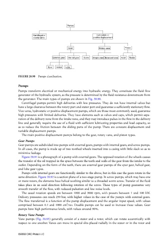
FIGURE 20.90 Pumps classification.
Pumps
Pumps transform electrical or mechanical energy into hydraulic energy. They constitute the fluid flow
generator of the hydraulic system, as the pressure is determined by the fluid resistance downstream from
the generator. The main types of pumps are shown in Fig. 20.90.
Centrifugal pumps permit high deliveries with low pressures. They do not have internal valves but
have a large clearance between the rotary part and stator part and guarantee a sufficiently stationary flow.
Vice versa, hydrostatic or positive displacement pumps, which are those most commonly used, guarantee
high pressures with limited deliveries. They have elements such as valves and caps, which permit sepa-
ration of the delivery zone from the intake zone, and they may introduce pulses in the flow in the delivery
line and generally require the use of a fluid with sufficient lubricating properties and load capacity, so
as to reduce the friction between the sliding parts of the pump. There are constant displacement and
variable displacement pumps.
The main positive displacement pumps belong to the gear, rotary vane, and piston types.
Gear Pumps
Gear pumps are subdivided into pumps with external gears, pumps with internal gears, and screw pumps.
In all cases, the pump is made up of two toothed wheels inserted into a casing with little slack so as to
minimize leakage.
Figure 20.91 is a photograph of a pump with external gears. The opposed rotation of the wheels causes
the transfer of the oil trapped in the space between the teeth and walls of the gear from the intake to the
outlet. Depending on the form of the teeth, there are external gear pumps of the spur gear, helical gear,
and lobe gear types.
Pumps with internal gears are functionally similar to the above, but in this case the gears rotate in the
same direction. Figure 20.92 is a section plane of a two-stage pump. In screw pumps, which may have one
or more rotors, the elements have helical toothing similar to a threaded worm screw. Transfer of the fluid
takes place in an axial direction following rotation of the screw. These types of pump guarantee very
smooth transfer of the flow, with reduced pulsation and low noise levels.
The usual rotation speeds are between 1000 and 3000 rpm, with powers between 1 and 100 kW.
Delivery pressures can reach 250 bar, with higher values in the case of the pumps with external gears.
The flow transferred is a function of the pump displacement and the angular input speed, with values
2
comprised between 0.1 and 1000 cm /rev. Double pumps can be used to increase these values. Gear
pumps have high performance levels, with values around 90%.
Rotary Vane Pumps
Vane pumps (Fig. 20.93) generally consist of a stator and a rotor, which can rotate eccentrically with
respect to one another. Vanes can move in special slits placed radially in the stator or in the rotor and
©2002 CRC Press LLC