
Page 601 - The Mechatronics Handbook
P. 601
0066_Frame_C20 Page 71 Wednesday, January 9, 2002 5:49 PM
a) b)
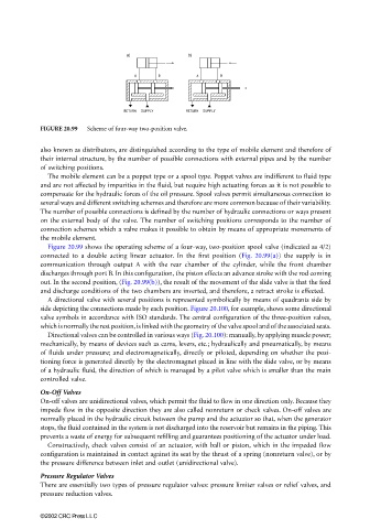
FIGURE 20.99 Scheme of four-way two-position valve.
also known as distributors, are distinguished according to the type of mobile element and therefore of
their internal structure, by the number of possible connections with external pipes and by the number
of switching positions.
The mobile element can be a poppet type or a spool type. Poppet valves are indifferent to fluid type
and are not affected by impurities in the fluid, but require high actuating forces as it is not possible to
compensate for the hydraulic forces of the oil pressure. Spool valves permit simultaneous connection to
several ways and different switching schemes and therefore are more common because of their variability.
The number of possible connections is defined by the number of hydraulic connections or ways present
on the external body of the valve. The number of switching positions corresponds to the number of
connection schemes which a valve makes it possible to obtain by means of appropriate movements of
the mobile element.
Figure 20.99 shows the operating scheme of a four-way, two-position spool valve (indicated as 4/2)
connected to a double acting linear actuator. In the first position (Fig. 20.99(a)) the supply is in
communication through output A with the rear chamber of the cylinder, while the front chamber
discharges through port B. In this configuration, the piston effects an advance stroke with the rod coming
out. In the second position, (Fig. 20.99(b)), the result of the movement of the slide valve is that the feed
and discharge conditions of the two chambers are inverted, and therefore, a retract stroke is effected.
A directional valve with several positions is represented symbolically by means of quadrants side by
side depicting the connections made by each position. Figure 20.100, for example, shows some directional
valve symbols in accordance with ISO standards. The central configuration of the three-position valves,
which is normally the rest position, is linked with the geometry of the valve spool and of the associated seats.
Directional valves can be controlled in various ways (Fig. 20.100): manually, by applying muscle power;
mechanically, by means of devices such as cams, levers, etc.; hydraulically and pneumatically, by means
of fluids under pressure; and electromagnetically, directly or piloted, depending on whether the posi-
tioning force is generated directly by the electromagnet placed in line with the slide valve, or by means
of a hydraulic fluid, the direction of which is managed by a pilot valve which is smaller than the main
controlled valve.
On-Off Valves
On-off valves are unidirectional valves, which permit the fluid to flow in one direction only. Because they
impede flow in the opposite direction they are also called nonreturn or check valves. On-off valves are
normally placed in the hydraulic circuit between the pump and the actuator so that, when the generator
stops, the fluid contained in the system is not discharged into the reservoir but remains in the piping. This
prevents a waste of energy for subsequent refilling and guarantees positioning of the actuator under load.
Constructively, check valves consist of an actuator, with ball or piston, which in the impeded flow
configuration is maintained in contact against its seat by the thrust of a spring (nonreturn valve), or by
the pressure difference between inlet and outlet (unidirectional valve).
Pressure Regulator Valves
There are essentially two types of pressure regulator valves: pressure limiter valves or relief valves, and
pressure reduction valves.
©2002 CRC Press LLC