
Page 603 - The Mechatronics Handbook
P. 603
0066_Frame_C20 Page 73 Wednesday, January 9, 2002 5:49 PM
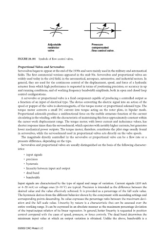
FIGURE 20.101 Symbols of flow control valves.
Proportional Valves and Servovalves
Servovalves began to appear at the end of the 1930s and were mainly used in the military and aeronautical
fields. The first commercial versions appeared in the mid-50s. Servovalves and proportional valves are
widely used today in the civil field, in the aeronautical, aerospace, automotive, and industrial sectors. In
general, they are used for the continuous control of the displacement, speed, and force of a hydraulic
actuator from which high performance is requested in terms of positioning precision, or accuracy in up
and running conditions, and of working frequency bandwidth amplitude, both in open and closed loop
control configurations.
A servovalve or proportional valve is a fluid component capable of producing a controlled output as
a function of an input of electrical type. The device converting the electric signal into an action of the
spool or poppet of the valve is electromagnetic, of the torque motor or proportional solenoid type. The
torque motor converts a small DC current into torque acting on the rotor plate, in bipolar mode.
Proportional solenoids produce a unidirectional force on the mobile armature function of the current
circulating in the winding, with the characteristic of maintaining this force approximately constant within
the cursor work displacement range. The torque motor, with lower current and inductance values, has
shorter response times than the servosolenoid, which operates with notably higher currents, but generates
lower mechanical power outputs. The torque motor, therefore, constitutes the pilot stage usually found
in servovalves, while the servosolenoid used in proportional valves acts directly on the valve spools.
The magnitude directly controlled by the servovalve or proportional valve can be a flow rate or a
pressure difference, depending on the type.
Servovalves and proportional valves are usually distinguished on the basis of the following character-
istics:
• input signals
• precision
• hysteresis
• linearity between input and output
• dead band
• bandwidth
Input signals are characterized by the type of signal and range of variation. Current signals (±10 mA
or 4–20 mA) or voltage ones (0–10 V) are typical. Precision is intended as the difference between the
desired value and the value effectively achieved. It is provided as a percentage of the full scale value.
The hysteresis derives from the different behavior shown by the component with ascending settings and
corresponding points descending. Its value expresses the percentage ratio between the maximum devi-
ation and the full scale value. Linearity by nature is a characteristic that can be assessed over the
entire working range. It can be expressed in an absolute manner as the maximum percentage deviation
of the input/output relation of its linear regression. In general, better linearity is requested in position
control compared with the cases of speed, pressure, or force controls. The dead band determines the
minimum input value at which an output variation is obtained. Unlike the above, bandwidth is a
©2002 CRC Press LLC