
Page 606 - The Mechatronics Handbook
P. 606
0066_Frame_C20 Page 76 Wednesday, January 9, 2002 5:49 PM
FIGURE 20.104 Block diagram of a jet-pipe servovalve.
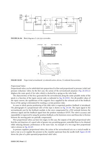
FIGURE 20.105 Proportional servosolenoid: (a) solenoid section scheme, (b) solenoid characteristics.
Proportional Valves
Proportional valves can be subdivided into proportional in flow and proportional in pressure (relief and
pressure reduction) valves. In the first case, the action of the servosolenoid armature (Fig. 20.105(a))
displaces the main spool of the valve, which is checked by a spring on the valve body.
The characteristics of the force generated by the servosolenoid, along the entire possible stroke of the
spool, is a function of the input current only, as indicated in Fig. 20.105(b). For all possible values of
the input current, the equilibrium of the magnetic force supplied by the solenoid and of the feedback
forces of the spring is determined by reaching a certain position value.
In cases in which precise positioning of the slide valve is requested, position feedback is introduced.
The photograph of a proportional valve of this type is shown in Fig. 20.106. The input signal to the
servosolenoid, sent by the feedback module, is the error compensated by a PID network between the
reference signal and the feedback signal from the position transducer LVDT. The valve’s accuracy and
repeatability is improved by using the position feedback, as the hysteresis errors and those due to friction
between the moving parts are partially compensated.
Flow proportional valves can have two stages. In this case, the outputs of the pilot proportional valve
feed the end chambers of a spool valve of greater size, permitting greater controlled flows to be obtained
while reducing dynamic performance at the same time. An example of a two-stage flow proportional
valve is shown in Fig. 20.107.
In pressure regulator proportional valves, the action of the servosolenoid acts on a conical needle in
such a way so as to regulate the pressure in the chamber upstream from the needle itself. Figure 20.108
shows the plan of a pilot operated proportional relief valve.
©2002 CRC Press LLC